This is the english version
Para a versão em português (pr-BR) use ESSE LINK
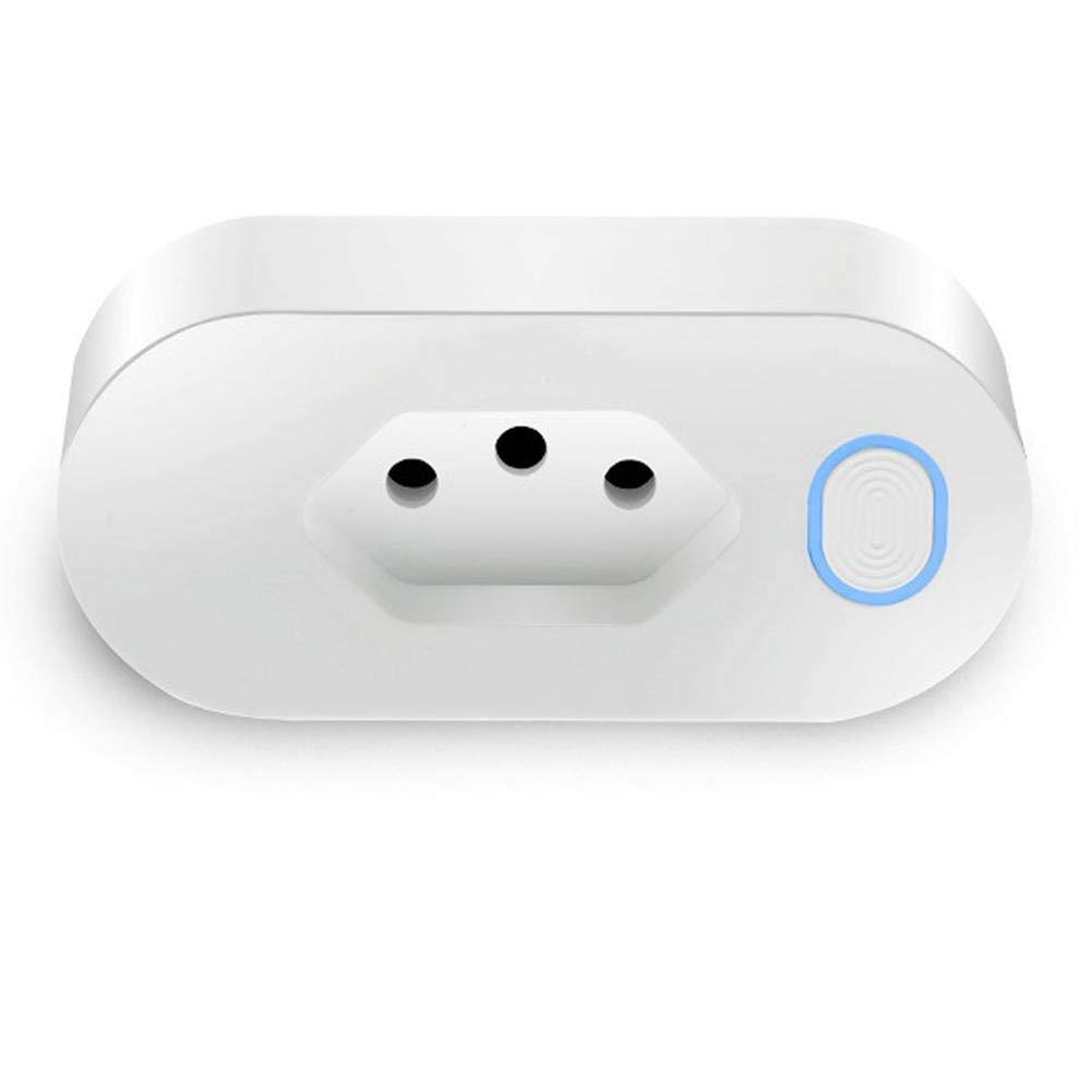
Recently, some smart plugs with the BR plug type started appearing on AliExpress
Usually, these products don't have a specific model and make, since they are mostly Tuya whitelables. After searching alot, I've found Nanxin NX-SM400 which looks like this one.
Since this model working with the Smart Life app, we know it uses a Tuya chip. To flash Tasmota, we need to us tuya-convert. There's an excellent tutorial (in pt-BR) by Douglas Baptista that you can use.
To configure the smart plug on Tasmota, we have to know how the ESP pins are connected. I had to open mine to check the connections. But you don't have to do the same. You can use this template that I've created.
Go to the device's IP address > Configuration > Configure Other > Template
{"NAME":"NX-SM400","GPIO":[0,0,0,17,134,132,0,0,130,52,21,0,0],"FLAG":0,"BASE":18}Just paste that line and check Activate

To create the template, I had to open the plug up.
If you want to do that, you can use a hot air gun on the bottom part and a flat head screwdriver to force it open. It will probably damage the case a little bit and you will need to glue it shut.


The smart plug uses the TYWE2S Tuya chip, which is a ESP8285.

The power monitoring chip is the BL0937 It's pins are connected like this:
| BL0937 | ESP8285 |
|---|---|
| Pin 6 (CF) | GPIO 4 |
| Pin 7 (CF1) | GPIO 5 |
| Pin 8 (SEL) | GPIO 12 |

The switch and LEDs are on another PCB. They are connected like this:
| PCB | ESP8285 |
|---|---|
| Red LED | GPIO 14 (Same as Relay) |
| Blue LED | GPIO 13 |
| Switch | GPIO 3 (Rx) |
At last, the Relay is connected to the GPIO14 pin.