Original blog post by Kako: http://www.kako.com/neta/2008-009/2008-009.html
Hand-translated to English by multiplemonomials
Last year (2007), I analyzed the Wii remote's infrared pointing sensor and tested out a method of controlling it from another machine. Continuing that, this time I attempted to make circuits to connect it to an Arduino dev kit that uses an AVR microcontroller. (4/13/2008)
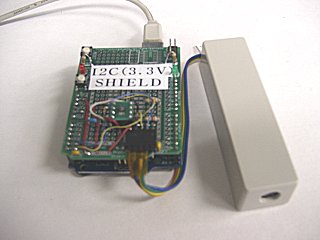
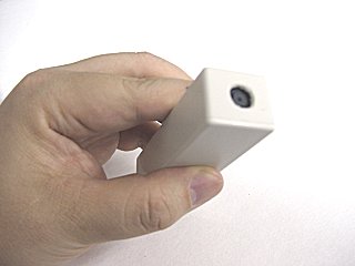
As for the PCB, for testing I stacked a breadboard on top of the Arduino. I put the sensor I took from the Wii remote plus my homemade circuit inside a white, bar-shaped case.
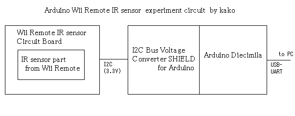
The connections were set up as in the diagram. I used these three parts:
- The Wii remote infrared sensor circuit
- I2C voltage conversion shield
- Arduino Diecimila To connect the IR sensor, which operates at 3.3V, to the microcontroller, which operates at 5V, a voltage converter is necessary.
I connected the Wii remote IR sensor to a miniaturized version of the circuit I made previously. I made the I2C voltage converter using a breadboard PCB for testing called the Prototype Shield.
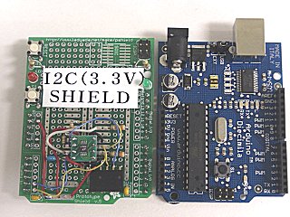
I hooked up the voltage conversion shield so it can be stacked directly on top of the Arduino.
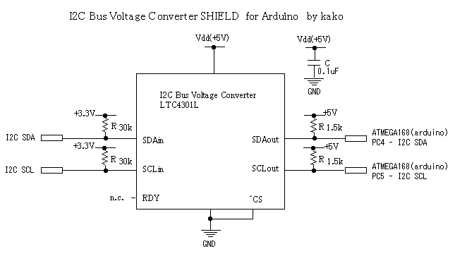
I made the conversion circuit using an IC called the LTC4301L, which changes the voltage of an I2C bus. If you don't have an LTC4301L, an LTC4301 should also work.
I prepared an Arduino version of the code from last time: wii_remote_ir_sensor_sample.zip - source code (download)
(Updated 9/21/2008) I updated the code for use with WinAVR: wii_remote_ir_sensor_sample2.zip - source code (download)
I'll try to explain simply how the sensor is used.
In standard I2C protocol, to communicate with a device, you have to transmit its address byte first. The address of the sensor in the Wii Remote is 0x58.
It will be written as 0xB0 in other places such as the source code, but this is just the shifted version where the upper 7 bits are the address and the lowest bit is the read / write indicator.
Initialization of the sensor is simpler than in "a method to access sensors inside the Wii remote via Bluetooth" because the chip enable and the clock circuit don't have to be controlled.
Commands to initialize the sensor are sent through the following process:
[Start condition] [0xB0] [Control register address] [Data to write] [Stop condition]
Addresses for the control registers are 8 bits. What address controls what function is still not known in detail. For now, if you write these predetermined values, the sensor can be operated.
- Write 0x01 to control register address 0x30.
- Write 0x08 to control register address 0x30.
- Write 0x90 to control register address 0x06.
- Write 0xC0 to control register address 0x08.
- Write 0x40 to control register address 0x1A.
- Write 0x33 to control register address 0x33.
As explained below, this seems to be a simplified way of configuring the sensitivity.
It seems to be simplified above, but if you want to configure it properly, you must take four parameters (p0 through p3) and write them to the sensor using the following process:
- Write 0x1 to control register 0x30.
- Write the following 7 bytes to control register 0x00: 0x02, 0x00, 0x00, 0x71, 0x01, 0x00, p0.
- Write the following 2 bytes to control register 0x07: 0x00, p1
- Write the following 2 bytes to control register 0x1A: p2, p3
- Write 0x03 to control register 0x33.
- Write 0x8 to control register address 0x30.
When you write multiple bytes, the address of the register being written to increments automatically. So, you can write all the bytes in a single I2C transaction.
The sensitivity parameters are:
| Sensitivity Level | p0 | p1 | p2 | p3 |
|---|---|---|---|---|
| 1 | 0x72 | 0x20 | 0x1F | 0x03 |
| 2 | 0xC8 | 0x36 | 0x35 | 0x3 |
| 3 | 0xAA | 0x64 | 0x63 | 0x03 |
| 4 | 0x96 | 0xB4 | 0xB3 | 0x04 |
| 5 | 0x96 | 0xFE | 0xFE | 0x05 |
After initialization (and configuring the sensitivity), you can read out the coordinates of detected points of light from the sensor.
[Start Condition] [0xB0] [0x36] [Stop Condition]
After sending that sequence, read the data using:
[Start Condition] [0xB1] [Read Data Byte]x16
The data is formatted as groups of three bytes:
[1 byte header] [Coordinate 1, 3 bytes] [Coordinate 2, 3 bytes] [Coordinate 3, 3 bytes] [Coordinate 4, 3 bytes]
If the values of the three coordinate bytes are XX, YY, and SS, the x coordinate is given by ((SS & 0x30) << 4) + XX, and the Y coordinate is given by ((SS & 0xC0) << 2) + YY.
[I think there's an issue with operator precedence in the previous line in the original. I added parenthesis to match how it is implemented in the sample code. -TR]
If the coordinates are unavailable, you will get 0x3FF for the values.
- Addresses 0x00 to 0x08 and addresses 0x1A to 0x1B -- parameters for detection
- Address 0x30 -- Operating mode of the sensor (?). 0x1 is written to it initially, then 0x8 later on.
- Address 0x33 -- Operating mode of the sensor (?). 0x3 (or 0x33) is written to it.
Still unknown.
Settings for the software inside the camera that allow it to process images and detect the luminous points on them. I'd guess these could be things like the threshold for splitting one point into two or the size threshold of points.
(Updated 10/6/2008) It looks like this site [changed to Internet Archive link -TN] is starting to identify a few of the registers, as well as various other information.
Last time, with the Wii Remote sitting on top of a table, I tested whether the infrared sensor inside the Wii Remote could detect motion left, right, forward, and backward. I lined up two sources of light horizontally, just like a genuine sensor bar
the precision to use it as a mouse was not there.