Skip to content

Instantly share code, notes, and snippets.

@probonopd
Last active March 26, 2024 18:55
Show Gist options
  • Star 3 You must be signed in to star a gist
  • Fork 2 You must be signed in to fork a gist
  • Save probonopd/c114ea42ea6fef5b6b6b6118ae49ebf8 to your computer and use it in GitHub Desktop.
Save probonopd/c114ea42ea6fef5b6b6b6118ae49ebf8 to your computer and use it in GitHub Desktop.
UPDATE: This project has been moved to https://github.com/probonopd/Lifestyle

Controlling 27.145 MHz BOSE Lifestyle with Raspberry Pi

I want to tie my BOSE Lifestyle system into my smart home control setup like this:

mute

The Remote Control RC9 for BOSE Lifestyle 3, 5, 8, 12 systems is using radio rather than infrared. Also, since these systems do not have other ways to control them, it is difficult to integrate them into home automation setups. Also, there are no replacement remotes available and even worn-down used original remotes go for absurd prices on eBay.

This is why I was curious how these devices could be controlled using the apparently proprietary radio signals.

From the manual, I knew that the device was using 27.145 MHz for the remote control. So I started by investigating the FCC database, searching for the manufacturer BOSE and the frequency 27.145 MHz. I did not find my exact model but others that suggested that BOSE was using 27.145 MHz pulses with on-off keying (OOK). According to Wikipedia, OOK denotes the simplest form of amplitude-shift keying (ASK) modulation that represents digital data at the presence or absence of a carrier wave. Some of the documents in the FCC database show sample pulse trains.

Teardown of original remote

rc9 raltron

  • BOSE PCB is HCMK-C2X
  • Main IC is NEC D6121G 001 0207D3001 (data sheet)
  • Ceramic Resonator is CSB 455J (430-519 kHz according to data sheet; needed by the NEC D6121G)
  • Crystal is RALTRON 27.145-30 02 CYH 04

Measured with Saleae Logic on D6121G pin 7 = REM

On pin 7 = REM, there is for the ON/OFF key an infrared-like signal modulated with 38 kHz and 33% duty cycle (yellow channel 4 below). The same signal but not modulated with 38 kHz can be seen at L2 near the transmitting antenna (orange channel 3 below).

If keys are pressed for a longer time, repetitions happen after 39 ms.

bildschirmfoto 2016-12-16 um 23 12 31

Zoom in a bit to see the difference between the signal modulated with 38 kHz and 33% duty cycle (yellow channel 4 below) and unmodulated at L2 near the transmitting antenna (orange channel 3 below).

bildschirmfoto 2016-12-16 um 23 14 51

Wait, these signals look familiar. This is a variant of the well-known NEC infrared protocol that is used by many infrared-controlled devices. In fact, the signal above is protocol = NEC2, device = 186, subdevice = 85, obc = 76. But instead of sending the signals using a 940 nm infrared LED pulsating at 38 kHz, they are using an antenna pulsating at 27.145 MHz for the periods marked with "+" below. I used the awesome IrScrutinizer tool to verify my hypothesis by generating some NEC codes. Then I checked the irdb infrared database, one of the largest crowd-sourced, manufacturer-independent databases of infrared remote control codes on the web. And indeed, I found this set of BOSE codes. Using IrScrutinizer, it was easy to calculate the "clean" (calculated rather than measured) codes for all BOSE commands.

Hence I assume that these are the valid signals in nanoseconds, with "+" being "27.145 MHz on", and "-" = off:

MUTE
+9024 -4512 +564 -564 +564 -1692 +564 -564 +564 -1692 +564 -1692 +564 -1692 +564 -564 +564 -1692 +564 -1692 +564 -564 +564 -1692 +564 -564 +564 -1692 +564 -564 +564 -1692 +564 -564 +564 -1692 +564 -564 +564 -564 +564 -564 +564 -564 +564 -564 +564 -564 +564 -564 +564 -564 +564 -1692 +564 -1692 +564 -1692 +564 -1692 +564 -1692 +564 -1692 +564 -1692 +564 -38628

VOLUME -
+9024 -4512 +564 -564 +564 -1692 +564 -564 +564 -1692 +564 -1692 +564 -1692 +564 -564 +564 -1692 +564 -1692 +564 -564 +564 -1692 +564 -564 +564 -1692 +564 -564 +564 -1692 +564 -564 +564 -564 +564 -1692 +564 -564 +564 -564 +564 -564 +564 -564 +564 -564 +564 -564 +564 -1692 +564 -564 +564 -1692 +564 -1692 +564 -1692 +564 -1692 +564 -1692 +564 -1692 +564 -38628

VOLUME +
+9024 -4512 +564 -564 +564 -1692 +564 -564 +564 -1692 +564 -1692 +564 -1692 +564 -564 +564 -1692 +564 -1692 +564 -564 +564 -1692 +564 -564 +564 -1692 +564 -564 +564 -1692 +564 -564 +564 -1692 +564 -1692 +564 -564 +564 -564 +564 -564 +564 -564 +564 -564 +564 -564 +564 -564 +564 -564 +564 -1692 +564 -1692 +564 -1692 +564 -1692 +564 -1692 +564 -1692 +564 -38628

AM/FM
+9024 -4512 +564 -564 +564 -1692 +564 -564 +564 -1692 +564 -1692 +564 -1692 +564 -564 +564 -1692 +564 -1692 +564 -564 +564 -1692 +564 -564 +564 -1692 +564 -564 +564 -1692 +564 -564 +564 -564 +564 -1692 +564 -1692 +564 -564 +564 -564 +564 -564 +564 -564 +564 -564 +564 -1692 +564 -564 +564 -564 +564 -1692 +564 -1692 +564 -1692 +564 -1692 +564 -1692 +564 -38628

SURROUND -
+9024 -4512 +564 -564 +564 -1692 +564 -564 +564 -1692 +564 -1692 +564 -1692 +564 -564 +564 -1692 +564 -1692 +564 -564 +564 -1692 +564 -564 +564 -1692 +564 -564 +564 -1692 +564 -564 +564 -564 +564 -1692 +564 -564 +564 -1692 +564 -564 +564 -564 +564 -564 +564 -564 +564 -1692 +564 -564 +564 -1692 +564 -564 +564 -1692 +564 -1692 +564 -1692 +564 -1692 +564 -38628

SURROUND +
+9024 -4512 +564 -564 +564 -1692 +564 -564 +564 -1692 +564 -1692 +564 -1692 +564 -564 +564 -1692 +564 -1692 +564 -564 +564 -1692 +564 -564 +564 -1692 +564 -564 +564 -1692 +564 -564 +564 -1692 +564 -1692 +564 -564 +564 -1692 +564 -564 +564 -564 +564 -564 +564 -564 +564 -564 +564 -564 +564 -1692 +564 -564 +564 -1692 +564 -1692 +564 -1692 +564 -1692 +564 -38628

VIDEO 2
+9024 -4512 +564 -564 +564 -1692 +564 -564 +564 -1692 +564 -1692 +564 -1692 +564 -564 +564 -1692 +564 -1692 +564 -564 +564 -1692 +564 -564 +564 -1692 +564 -564 +564 -1692 +564 -564 +564 -1692 +564 -564 +564 -1692 +564 -1692 +564 -564 +564 -564 +564 -564 +564 -564 +564 -564 +564 -1692 +564 -564 +564 -564 +564 -1692 +564 -1692 +564 -1692 +564 -1692 +564 -38628

VIDEO 1
+9024 -4512 +564 -564 +564 -1692 +564 -564 +564 -1692 +564 -1692 +564 -1692 +564 -564 +564 -1692 +564 -1692 +564 -564 +564 -1692 +564 -564 +564 -1692 +564 -564 +564 -1692 +564 -564 +564 -564 +564 -1692 +564 -1692 +564 -1692 +564 -564 +564 -564 +564 -564 +564 -564 +564 -1692 +564 -564 +564 -564 +564 -564 +564 -1692 +564 -1692 +564 -1692 +564 -1692 +564 -38628

AUX
+9024 -4512 +564 -564 +564 -1692 +564 -564 +564 -1692 +564 -1692 +564 -1692 +564 -564 +564 -1692 +564 -1692 +564 -564 +564 -1692 +564 -564 +564 -1692 +564 -564 +564 -1692 +564 -564 +564 -1692 +564 -1692 +564 -1692 +564 -1692 +564 -564 +564 -564 +564 -564 +564 -564 +564 -564 +564 -564 +564 -564 +564 -564 +564 -1692 +564 -1692 +564 -1692 +564 -1692 +564 -38628

SKIP <<
+9024 -4512 +564 -564 +564 -1692 +564 -564 +564 -1692 +564 -1692 +564 -1692 +564 -564 +564 -1692 +564 -1692 +564 -564 +564 -1692 +564 -564 +564 -1692 +564 -564 +564 -1692 +564 -564 +564 -564 +564 -564 +564 -564 +564 -1692 +564 -1692 +564 -564 +564 -564 +564 -564 +564 -1692 +564 -1692 +564 -1692 +564 -564 +564 -564 +564 -1692 +564 -1692 +564 -1692 +564 -38628

SKIP >>
+9024 -4512 +564 -564 +564 -1692 +564 -564 +564 -1692 +564 -1692 +564 -1692 +564 -564 +564 -1692 +564 -1692 +564 -564 +564 -1692 +564 -564 +564 -1692 +564 -564 +564 -1692 +564 -564 +564 -1692 +564 -564 +564 -564 +564 -1692 +564 -1692 +564 -564 +564 -564 +564 -564 +564 -564 +564 -1692 +564 -1692 +564 -564 +564 -564 +564 -1692 +564 -1692 +564 -1692 +564 -38628

STOP
+9024 -4512 +564 -564 +564 -1692 +564 -564 +564 -1692 +564 -1692 +564 -1692 +564 -564 +564 -1692 +564 -1692 +564 -564 +564 -1692 +564 -564 +564 -1692 +564 -564 +564 -1692 +564 -564 +564 -564 +564 -1692 +564 -564 +564 -1692 +564 -1692 +564 -564 +564 -564 +564 -564 +564 -1692 +564 -564 +564 -1692 +564 -564 +564 -564 +564 -1692 +564 -1692 +564 -1692 +564 -38628

2 SP
+9024 -4512 +564 -564 +564 -1692 +564 -564 +564 -1692 +564 -1692 +564 -1692 +564 -564 +564 -1692 +564 -1692 +564 -564 +564 -1692 +564 -564 +564 -1692 +564 -564 +564 -1692 +564 -564 +564 -1692 +564 -1692 +564 -564 +564 -1692 +564 -564 +564 -564 +564 -1692 +564 -564 +564 -564 +564 -564 +564 -1692 +564 -564 +564 -1692 +564 -1692 +564 -564 +564 -1692 +564 -38628

ON/OFF
+9024 -4512 +564 -564 +564 -1692 +564 -564 +564 -1692 +564 -1692 +564 -1692 +564 -564 +564 -1692 +564 -1692 +564 -564 +564 -1692 +564 -564 +564 -1692 +564 -564 +564 -1692 +564 -564 +564 -564 +564 -564 +564 -1692 +564 -1692 +564 -564 +564 -564 +564 -1692 +564 -564 +564 -1692 +564 -1692 +564 -564 +564 -564 +564 -1692 +564 -1692 +564 -564 +564 -1692 +564 -38628

5 SP
+9024 -4512 +564 -564 +564 -1692 +564 -564 +564 -1692 +564 -1692 +564 -1692 +564 -564 +564 -1692 +564 -1692 +564 -564 +564 -1692 +564 -564 +564 -1692 +564 -564 +564 -1692 +564 -564 +564 -564 +564 -1692 +564 -1692 +564 -1692 +564 -564 +564 -564 +564 -1692 +564 -564 +564 -1692 +564 -564 +564 -564 +564 -564 +564 -1692 +564 -1692 +564 -564 +564 -1692 +564 -38628

3 SP
+9024 -4512 +564 -564 +564 -1692 +564 -564 +564 -1692 +564 -1692 +564 -1692 +564 -564 +564 -1692 +564 -1692 +564 -564 +564 -1692 +564 -564 +564 -1692 +564 -564 +564 -1692 +564 -564 +564 -1692 +564 -1692 +564 -1692 +564 -1692 +564 -564 +564 -564 +564 -1692 +564 -564 +564 -564 +564 -564 +564 -564 +564 -564 +564 -1692 +564 -1692 +564 -564 +564 -1692 +564 -38628

TAPE
+9024 -4512 +564 -564 +564 -1692 +564 -564 +564 -1692 +564 -1692 +564 -1692 +564 -564 +564 -1692 +564 -1692 +564 -564 +564 -1692 +564 -564 +564 -1692 +564 -564 +564 -1692 +564 -564 +564 -564 +564 -1692 +564 -564 +564 -564 +564 -1692 +564 -564 +564 -1692 +564 -564 +564 -1692 +564 -564 +564 -1692 +564 -1692 +564 -564 +564 -1692 +564 -564 +564 -1692 +564 -38628

CD
+9024 -4512 +564 -564 +564 -1692 +564 -564 +564 -1692 +564 -1692 +564 -1692 +564 -564 +564 -1692 +564 -1692 +564 -564 +564 -1692 +564 -564 +564 -1692 +564 -564 +564 -1692 +564 -564 +564 -1692 +564 -1692 +564 -564 +564 -564 +564 -1692 +564 -564 +564 -1692 +564 -564 +564 -564 +564 -564 +564 -1692 +564 -1692 +564 -564 +564 -1692 +564 -564 +564 -1692 +564 -38628

PLAY
+9024 -4512 +564 -564 +564 -1692 +564 -564 +564 -1692 +564 -1692 +564 -1692 +564 -564 +564 -1692 +564 -1692 +564 -564 +564 -1692 +564 -564 +564 -1692 +564 -564 +564 -1692 +564 -564 +564 -1692 +564 -564 +564 -1692 +564 -564 +564 -1692 +564 -564 +564 -1692 +564 -564 +564 -564 +564 -1692 +564 -564 +564 -1692 +564 -564 +564 -1692 +564 -564 +564 -1692 +564 -38628

PAUSE
+9024 -4512 +564 -564 +564 -1692 +564 -564 +564 -1692 +564 -1692 +564 -1692 +564 -564 +564 -1692 +564 -1692 +564 -564 +564 -1692 +564 -564 +564 -1692 +564 -564 +564 -1692 +564 -564 +564 -564 +564 -1692 +564 -1692 +564 -564 +564 -1692 +564 -564 +564 -1692 +564 -564 +564 -1692 +564 -564 +564 -564 +564 -1692 +564 -564 +564 -1692 +564 -564 +564 -1692 +564 -38628

RANDOM
+9024 -4512 +564 -564 +564 -1692 +564 -564 +564 -1692 +564 -1692 +564 -1692 +564 -564 +564 -1692 +564 -1692 +564 -564 +564 -1692 +564 -564 +564 -1692 +564 -564 +564 -1692 +564 -564 +564 -564 +564 -564 +564 -1692 +564 -1692 +564 -1692 +564 -564 +564 -1692 +564 -564 +564 -1692 +564 -1692 +564 -564 +564 -564 +564 -564 +564 -1692 +564 -564 +564 -1692 +564 -38628

NEXT DISC
+9024 -4512 +564 -564 +564 -1692 +564 -564 +564 -1692 +564 -1692 +564 -1692 +564 -564 +564 -1692 +564 -1692 +564 -564 +564 -1692 +564 -564 +564 -1692 +564 -564 +564 -1692 +564 -564 +564 -1692 +564 -564 +564 -1692 +564 -1692 +564 -1692 +564 -564 +564 -1692 +564 -564 +564 -564 +564 -1692 +564 -564 +564 -564 +564 -564 +564 -1692 +564 -564 +564 -1692 +564 -38628

MUTE ALL
+9024 -4512 +564 -564 +564 -1692 +564 -564 +564 -1692 +564 -1692 +564 -1692 +564 -564 +564 -1692 +564 -1692 +564 -564 +564 -1692 +564 -564 +564 -1692 +564 -564 +564 -1692 +564 -564 +564 -1692 +564 -1692 +564 -1692 +564 -1692 +564 -1692 +564 -564 +564 -1692 +564 -1692 +564 -564 +564 -564 +564 -564 +564 -564 +564 -564 +564 -1692 +564 -564 +564 -564 +564 -38628

In other words:

MUTE: NEC2 Device: 186.85 Function: 1 S=85
VOLUME -: NEC2 Device: 186.85 Function: 2 S=85
VOLUME +: NEC2 Device: 186.85 Function: 3 S=85
AM/FM: NEC2 Device: 186.85 Function: 6 S=85
SURROUND -: NEC2 Device: 186.85 Function: 10 S=85
SURROUND +: NEC2 Device: 186.85 Function: 11 S=85
VIDEO 2: NEC2 Device: 186.85 Function: 13 S=85
VIDEO 1: NEC2 Device: 186.85 Function: 14 S=85
AUX: NEC2 Device: 186.85 Function: 15 S=85
SKIP <<: NEC2 Device: 186.85 Function: 24 S=85
SKIP >>: NEC2 Device: 186.85 Function: 25 S=85
STOP: NEC2 Device: 186.85 Function: 26 S=85
2 SP: NEC2 Device: 186.85 Function: 75 S=85
ON/OFF: NEC2 Device: 186.85 Function: 76 S=85
5 SP: NEC2 Device: 186.85 Function: 78 S=85
3 SP: NEC2 Device: 186.85 Function: 79 S=85
TAPE: NEC2 Device: 186.85 Function: 82 S=85
CD: NEC2 Device: 186.85 Function: 83 S=85
PLAY: NEC2 Device: 186.85 Function: 85 S=85
PAUSE: NEC2 Device: 186.85 Function: 86 S=85
RANDOM: NEC2 Device: 186.85 Function: 92 S=85
NEXT DISC: NEC2 Device: 186.85 Function: 93 S=85
MUTE ALL: NEC2 Device: 186.85 Function: 223 S=85

Analyzing these signals on the air

Analyzing the signal timing on the original remote is possible using a Saleae Logic Analyzer as shown above. But once I had built my own sender, I wanted to measure the signal on the air. In hindsight, it would not have been necessary to open the original remote, but I was curious what was inside anyway.

Analyzing the signal timing on the air is possible with an RTL SDR dongle, gqrx, and Audacity.

You can verify that something is sent on the frequency using the waterfall chart in gqrx. I used the Gqrx-2.6-1.glibc2.17-x86_64.AppImage on Linux. Because the application is provided by its author as an AppImage, I just had to download, chmod a+x ./Gqrx* and run.

gqrx_wf_20161127_153832

But gqrx is not suitable to really show the details of the protocol. So using gqrx, I converted the signals to audio. I played around with the settings until I heared clear "blip, blip" signals when I pressed keys on the remote. Then I recorded the audio. Then opened the audio in Audacity which is also available for Linux as a convenient AppImage. Looks like this:

Audacity

Bingo, the signal!

Generating these signals with Raspberry Pi

Known to work!

How could I possibly generate these signals with only household items that I had already lying around?

Here user joyceda suggested back in 2013:

I was wondering if this PiFm 'hack' http://www.icrobotics.co.uk/wiki/index.php/Turning_the_Raspberry_Pi_Into_an_FM_Transmitter38 , an rtl-sdr and a 20 cm piece of wire would help to provide a generic RC tranciever unit for a ninjablock. At present it seems that this is limited 1Mhz up to 250Mhz - so my Bose is in

So I gave it a try, and what should I say: It works using https://github.com/bskari/pi-rc and a long (ca. 50 cm - not yet optimized!) antenna. (In the beginning I tried with a 15 cm antenna and it would only work when I would touch the antenna.)

sudo ./pi_pcm -v
cat mute.json > /dev/udp/127.0.0.1/12345

This is the contents of mute.json, which is a representation of the MUTE timings +9024 -4512 +564 -564 +564 -1692 +564 -564 +564 -1692 +564 -1692 +564 -1692 +564 -564 +564 -1692 +564 -1692 +564 -564 +564 -1692 +564 -564 +564 -1692 +564 -564 +564 -1692 +564 -564 +564 -1692 +564 -564 +564 -564 +564 -564 +564 -564 +564 -564 +564 -564 +564 -564 +564 -564 +564 -1692 +564 -1692 +564 -1692 +564 -1692 +564 -1692 +564 -1692 +564 -1692 +564 -38628:

[
    {
        "frequency": 27.145,
        "dead_frequency": 49.830,
        "burst_us": 9024,
        "spacing_us": 4512,
        "repeats": 1
    },
    {
        "frequency": 27.145,
        "dead_frequency": 49.830,
        "burst_us": 564,
        "spacing_us": 564,
        "repeats": 1
    },
    {
        "frequency": 27.145,
        "dead_frequency": 49.830,
        "burst_us": 564,
        "spacing_us": 1692,
        "repeats": 1
    },
    {
        "frequency": 27.145,
        "dead_frequency": 49.830,
        "burst_us": 564,
        "spacing_us": 564,
        "repeats": 1
    },
    {
        "frequency": 27.145,
        "dead_frequency": 49.830,
        "burst_us": 564,
        "spacing_us": 1692,
        "repeats": 3
    },
    {
        "frequency": 27.145,
        "dead_frequency": 49.830,
        "burst_us": 564,
        "spacing_us": 564,
        "repeats": 1
    },
    {
        "frequency": 27.145,
        "dead_frequency": 49.830,
        "burst_us": 564,
        "spacing_us": 1692,
        "repeats": 2
    },
    {
        "frequency": 27.145,
        "dead_frequency": 49.830,
        "burst_us": 564,
        "spacing_us": 564,
        "repeats": 1
    },
    {
        "frequency": 27.145,
        "dead_frequency": 49.830,
        "burst_us": 564,
        "spacing_us": 1692,
        "repeats": 1
    },
    {
        "frequency": 27.145,
        "dead_frequency": 49.830,
        "burst_us": 564,
        "spacing_us": 564,
        "repeats": 1
    },
    {
        "frequency": 27.145,
        "dead_frequency": 49.830,
        "burst_us": 564,
        "spacing_us": 1692,
        "repeats": 1
    },
    {
        "frequency": 27.145,
        "dead_frequency": 49.830,
        "burst_us": 564,
        "spacing_us": 564,
        "repeats": 1
    },
    {
        "frequency": 27.145,
        "dead_frequency": 49.830,
        "burst_us": 564,
        "spacing_us": 1692,
        "repeats": 1
    },
    {
        "frequency": 27.145,
        "dead_frequency": 49.830,
        "burst_us": 564,
        "spacing_us": 564,
        "repeats": 1
    },
    {
        "frequency": 27.145,
        "dead_frequency": 49.830,
        "burst_us": 564,
        "spacing_us": 1692,
        "repeats": 1
    },
    {
        "frequency": 27.145,
        "dead_frequency": 49.830,
        "burst_us": 564,
        "spacing_us": 564,
        "repeats": 8
    },
    {
        "frequency": 27.145,
        "dead_frequency": 49.830,
        "burst_us": 564,
        "spacing_us": 1692,
        "repeats": 7
    },
    {
        "frequency": 27.145,
        "dead_frequency": 49.830,
        "burst_us": 564,
        "spacing_us": 1692000, 
        "repeats": 1
    }
]

To make things simpler, I wrote the bosecontrol.c code below which works for me when the Raspberry Pi 1 is running at its normal 700 MHz frequency. Underclocking it results in the code not working. Using something like DMA rather than the CPU to do the switching would be much better (can you do it?).

Ideas for further investigation

Being able to control a 27.145 MHz BOSE Lifestyle system with a Raspberry Pi may be a great proof-of-concept, but is not very practical for productive use (i.e., to be hidden permanently beyond the audio system as an additional way to control it):

  • The Raspberry Pi is overkill
  • The Raspberry Pi takes too long to boot
  • The Raspberry Pi consumes too much power for "just a remote control receiver"
  • The Raspberry Pi is large
  • The Raspberry Pi doesn't have WLAN built in

Hence, I am looking for a different solution.

Generating these signals with Arudino

Might be possible with a AD9850 module http://blog.riyas.org/2014/06/computer-controlling-27mhz-remote-control-car-ad9850-dds.html

Or with a Si4012. The Si4012 is a fully integrated FSK/OOK crystal-less CMOS high-data rate RF transmitter designed for the sub-GHz ISM band. http://www.silabs.com/products/wireless/EZRadio/Pages/si4012.aspx

Or with a LTC6903 Port Programmable Oscillator which can do 1 kHz to 68 MHz.

Or with a crystal. Similar to this circuit but using an Arduino instead of 5N555.

According to the Schematic, the minimal BOM needed seems to be

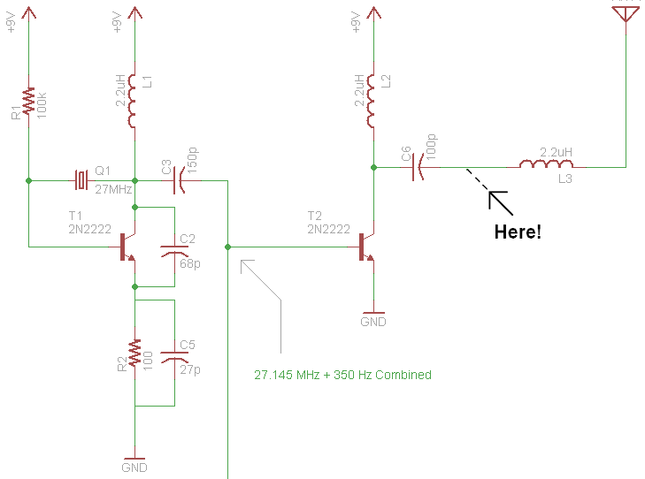
  • Need PCB, no Breadboard (since RF)
  • 27.145 MHz Crystal
  • 2x 2N2222 Transistors
  • 100kΩ Resistor
  • 100Ω Resistor
  • 27pF Capacitor
  • 68pF Capacitor
  • 100pF Capacitor
  • 150pF Capacitor
  • 3x 2.2uH Inductor Choke

I have not tried this yet due to the lack of hardware. Please let me know if you do.

RC Toys seem to use the TX-2B chip (which we could replace with an Arudino) and this more elaborate circuit:

circuit

Seems to be relatively complex. Coils? Inductors? Is that really all needed? probably the extra component are for filtering, which may be advisable.

I searched eBay for ready-to-use modules, but unlike for 433 MHz, readymade modules for this frequency seem not to exist. Why is this?

Generating these signals with ESP8266

It works with something along the lines of https://github.com/cnlohr/channel3, with esp8266/Arduino that lets us use the familiar Arduino toolset. Sketch below.

Someone is doing something very similar but for 433 MHz at https://github.com/papadeltasierra/dma433

However, it generates many other frequencies as well, so this is not a clean solution. The sender with a 30 cm long wire as an antenna on pin RX needs to be placed not too far from the music center.

Other ways to generate the signal on the cheap

  • Buy a garage door opener sender and try to attach it to an Arudino to replay the BOSE signals?
  • ...

Let me know if you are trying some of these or have other ideas.

Other investigations into the system

Teardown of the Control unit

The bose Lifestyle 8 Series II (2001) system consists of

  • "Lifestyle® music center" (control unit with built-in tuner and CD player)
  • "Acoustimass module" (subwoofer with integrated amplifier and bass/treble control dials)
  • 5 cube Speakers

The music center has as its main ICs:

  • SANYO LA1836 Single-Chip Home Stereo Electronic Tuning IC
  • SANYO LA6541 4-channel Bridge Driver for Compact Discs
  • SANYO LA9241M Analog Signal Processor (ASP) for CD players
  • SANYO LC78622E Compact Disc Player DSP ("realizes an optimal cost-performance tradeoff for low-end players by strictly limiting functionality to basic signal-processing and servo system functionality") - BOSE = low-end?!?
  • SANYO 72131 AM/FM PLL Frequency Synthesizer
  • ST TDA7309 Digital Controlled Stereo Audio Processor with Loudness. "The TDA7309 is a control processor with independent left and right volume control for quality audio applications. Selectable external loudness and soft mute functions are provided. Control is accomplished by serial I2C bus microprocessor interface."
  • ST TDA7310 Serial Bus Controlled Audio Processor "The TDA7310 is a volume, tone (bass and treble) and fader (front/rear) processor for high quality audio applications in car radio and Hi-Fi systems. Loudness and selectable input gain are provided. The control of all fuctions is accomplished by serial bus microprocessor interface."
  • ALPS 191401-001 Tuner?

I did not find a general purpose MCU but I did not take the boards out, possibly it is on the other side of the PCB.

Where is the BOSE secret sauce hiding?

Running the Acoustimass module without the music center

Officially the music center is needed to run the Acoustimass module and its connected speakers. The music center is used to switch on/off the device and set the volume, balance etc. But the input to the Acoustimass module consists of a proprietary "Audio input" connector that has on the other end

  • Cinch stereo cable (regular analog signal, presumably)
  • 3-pin "System control" (this we could possibly emulate using an Arduino if we knew the protocol - please let me know if you do, e.g., measure it with an oscilloscope and if signals are below 5V check with a Logic Analyzer; is it similar to US Patent 2005/0289224 A1?) (3.5 mm headphones-like connector)
  • Digital input cinch female input

According to this thread, the pinout is like this. (I still need to verify that thiss really applies for the Lifestyle 8 Series II).

Here is the Acoustimass module side:

Pinout

On the music center side:

You will need a pair of shielded phono cables for the left and right audio inputs and a stereo 3.5mm phone plug and 2 conductor shielded cable for the control/data cable. The tip of the phone plug will connect to pin 12 on the AM800P din plug, the ring of the phone plug to pin 7, and the shaft (shield) connects to pin 3. For the audio cables, left signal to pin 9, right signal to pin 1 and both shields to pin 5. Also jumper pins 2,3,6 and 10 together. They are all ground but do not connect them to pin 5, leave that connected to the signal ground only.

I might also mention here that the 10-12V turn-on voltage is NOT an absolute necessity. The AM5P has two power supplies and one is always on when the sub is connected to AC.(Unless it's a 220/240V version which has a power switch that must be on also.) You can either power the sub on using an applied voltage (10-12VDC) to pin 1 of the DIN connector or simply rely on the "Audio Sense" circuitry to power the sub on in the presence of an audio signal. The sub will power down to standby mode after about two minutes of a "no signal" condition.

With "phone plug" I assume they mean a 3.5 mm "headphone" jack.

Controlling the music center with a infrared remote control

Now that we know that the music center operates with NEC2 codes but uses RF rather than IR to submit them, I am curious whether we could hook up an infrared receiver (e.g., Vishay TSOPxxxx) instead of/in addition to the RF receiver built into the music center. However, I was not able to identify the RF receiver inside the music center but I did not take the boards out, possibly it is on the other side of the PCB.

What I DID find, to my surprise, was an unpopulated 3-pin connector J400 close to the display, and, even more interestingly, mounting holes for a 3-pin device right Q400 in front of the PCB where the locical location for an infrared receiver would be, with silkscreen suggesting a device looking very much like an infrared receiver (e.g., Vishay TSOPxxxx). When I place one there, it matches up perfectly. Unfortunately the traces are on the other side of the PCB so I could not trace them. I did not take the boards out. Could it be that BOSE engineers designed the PCB for an optional infrared receiver which then was left out in the end to save a few cents or make for a cleaner front housing design? Can we put one in there?

Providing digital sound

The manual says: "If your Lifestyle® system receives a valid digital signal (including PCM or Dolby Digital bitstreams), this digital sound is used."

Questions:

  • How do I provide this from a ALSA USB sound card? To be investigated.
  • Do I need a USB sound card with a SPDIF output?
  • How do I need to configure ALSA?
  • Is "Dolby Digital" == "AC3"?

Please let me know if you know.

Looks like I need IEC958: "To enable SPDIF output, you need to turn on “IEC958 Output Switch” control via mixer or alsactl (“IEC958” is the official name of so-called S/PDIF)." https://01.org/linuxgraphics/gfx-docs/drm/sound/cards/cmipci.html

A "HDMI Audio Extractor" may be able to extract the required signal from a Raspberry Pi... are there easier ways?

A "PCM2704 USB DAC to S/PDIF Sound Card Decoder Board" from China for under 5 USD may do it too. I ordered one for 3.58 USD called "5V USB Powered PCM2704 MINI USB Sound Card DAC decoder board for PC Computer T9". I will have to solder to pin 5 of the IC. Didn't like the bulkier (and more expensive) ones which require a old-school USB cable.

/*
Control BOSE using a 30 cm wire as antenna on GPIO_4 pin 7 on a Rasperry Pi 1
To compile:
gcc -Wall -O4 -o bosecontrol bosecontrol.c -std=gnu99 -lm
This file contains parts of code from Pifm.c by Oliver Mattos and Oskar Weigl
This program is free software; you can redistribute it and/or modify
it under the terms of the GNU General Public License as published by
the Free Software Foundation; either version 2 of the License, or
(at your option) any later version.
This program is distributed in the hope that it will be useful,
but WITHOUT ANY WARRANTY; without even the implied warranty of
MERCHANTABILITY or FITNESS FOR A PARTICULAR PURPOSE. See the
GNU General Public License for more details.
You should have received a copy of the GNU General Public License
along with this program; if not, write to the Free Software
Foundation, Inc., 675 Mass Ave, Cambridge, MA 02139, USA.
*/
#include <stdio.h>
#include <string.h>
#include <stdlib.h>
#include <dirent.h>
#include <math.h>
#include <fcntl.h>
#include <assert.h>
#include <malloc.h>
#include <sys/mman.h>
#include <sys/types.h>
#include <sys/stat.h>
#include <signal.h>
#include <unistd.h>
#include <getopt.h>
#include <stdint.h>
#include <time.h>
#include <getopt.h>
#include <ctype.h>
#include <errno.h>
#include <fcntl.h>
#define PAGE_SIZE (4*1024)
#define BLOCK_SIZE (4*1024)
int mem_fd;
char *gpio_mem, *gpio_map;
char *spi0_mem, *spi0_map;
double ppm_correction;
double pllo_frequency;
//#define PLL0_FREQUENCY 250000000.0
#define PLL0_FREQUENCY 500000000.0
#define BCM2708_PERI_BASE 0x20000000
#define GPIO_BASE (BCM2708_PERI_BASE + 0x200000) /* GPIO controller */
// I/O access
volatile unsigned *gpio;
volatile unsigned *allof7e;
// GPIO setup macros. Always use INP_GPIO(x) before using OUT_GPIO(x) or SET_GPIO_ALT(x,y)
#define INP_GPIO(g) *(gpio+((g)/10)) &= ~(7<<(((g)%10)*3))
#define OUT_GPIO(g) *(gpio+((g)/10)) |= (1<<(((g)%10)*3))
#define SET_GPIO_ALT(g,a) *(gpio+(((g)/10))) |= (((a)<=3?(a)+4:(a)==4?3:2)<<(((g)%10)*3))
#define GPIO_SET *(gpio+7) // sets bits which are 1 ignores bits which are 0
#define GPIO_CLR *(gpio+10) // clears bits which are 1 ignores bits which are 0
#define GPIO_GET *(gpio+13) // sets bits which are 1 ignores bits which are 0
#define ACCESS(base) *(volatile int*)((int)allof7e+base-0x7e000000)
#define SETBIT(base, bit) ACCESS(base) |= 1<<bit
#define CLRBIT(base, bit) ACCESS(base) &= ~(1<<bit)
#define CM_GP0CTL (0x7e101070)
#define GPFSEL0 (0x7E200000)
#define CM_GP0DIV (0x7e101074)
#define CLKBASE (0x7E101000)
#define DMABASE (0x7E007000)
#define START_IN 8
#define TRIGGER_OUT 17
struct GPCTL
{
char SRC : 4;
char ENAB : 1;
char KILL : 1;
char : 1;
char BUSY : 1;
char FLIP : 1;
char MASH : 2;
unsigned int : 13;
char PASSWD : 8;
};
int verbose;
// Set up a memory regions to access GPIO
void setup_io()
{
/* open /dev/mem */
if ((mem_fd = open("/dev/mem", O_RDWR|O_SYNC) ) < 0)
{
printf("can't open /dev/mem, need to run as root\n");
exit(-1);
}
/* mmap GPIO */
gpio_map = mmap(
NULL, // Any adddress in our space will do
BLOCK_SIZE, // Map length
PROT_READ|PROT_WRITE,// Enable reading & writting to mapped memory
MAP_SHARED, // Shared with other processes
mem_fd, // File to map
GPIO_BASE // Offset to GPIO peripheral
);
close(mem_fd); // No need to keep mem_fd open after mmap
if(gpio_map == MAP_FAILED)
{
printf("mmap error %d\n", (int)gpio_map); // errno also set!
exit(-1);
}
// Always use volatile pointer!
gpio = (volatile unsigned *)gpio_map;
} /* end function setup_io */
void set_gpio_directions()
{
// TRIGGER_OUT to output
INP_GPIO(TRIGGER_OUT);
OUT_GPIO(TRIGGER_OUT);
} /* end function set_gpio_directions */
void getRealMemPage(void** vAddr, void** pAddr)
{
void* a = valloc(4096);
((int*)a)[0] = 1; // use page to force allocation
mlock(a, 4096); // lock into ram
*vAddr = a; // yay - we know the virtual address
unsigned long long frameinfo;
int fp = open("/proc/self/pagemap", 'r');
lseek(fp, ((int)a)/4096*8, SEEK_SET);
read(fp, &frameinfo, sizeof(frameinfo));
*pAddr = (void*)((int)(frameinfo*4096));
}
void freeRealMemPage(void* vAddr)
{
munlock(vAddr, 4096); // unlock ram.
free(vAddr);
}
void start_rf_output(int source)
{
/* open /dev/mem */
if( (mem_fd = open("/dev/mem", O_RDWR|O_SYNC) ) < 0)
{
fprintf(stderr, "freq_pi: can't open /dev/mem, aborting.\n");
exit (1);
}
allof7e = (unsigned *)mmap( NULL, 0x01000000, /*len */ PROT_READ|PROT_WRITE, MAP_SHARED, mem_fd, 0x20000000 /* base */ );
if( (int)allof7e == -1) exit(1);
SETBIT(GPFSEL0 , 14);
CLRBIT(GPFSEL0 , 13);
CLRBIT(GPFSEL0 , 12);
struct GPCTL setupword = {source, 1, 0, 0, 0, 1,0x5a};
ACCESS(CM_GP0CTL) = *((int*)&setupword);
}
void modulate(int m)
{
ACCESS(CM_GP0DIV) = (0x5a << 24) + 0x4d72 + m;
}
struct CB
{
volatile unsigned int TI;
volatile unsigned int SOURCE_AD;
volatile unsigned int DEST_AD;
volatile unsigned int TXFR_LEN;
volatile unsigned int STRIDE;
volatile unsigned int NEXTCONBK;
volatile unsigned int RES1;
volatile unsigned int RES2;
};
struct DMAregs
{
volatile unsigned int CS;
volatile unsigned int CONBLK_AD;
volatile unsigned int TI;
volatile unsigned int SOURCE_AD;
volatile unsigned int DEST_AD;
volatile unsigned int TXFR_LEN;
volatile unsigned int STRIDE;
volatile unsigned int NEXTCONBK;
volatile unsigned int DEBUG;
};
struct PageInfo
{
void* p; // physical address
void* v; // virtual address
};
struct PageInfo constPage;
struct PageInfo instrPage;
struct PageInfo instrs[1024];
int set_frequency(uint32_t frequency)
{
if(verbose)
{
fprintf(stderr, "set_frequency(): arg frequency=%d\n", frequency);
}
uint32_t ua;
uint16_t divi; // integer part divider [23:12] 12 bits wide, max 4095
uint16_t divf; // fractional part divider [11:0] 12 bits wide, max 4095
/* set frequeny */
/* calculate divider */
double da;
da = pllo_frequency;
da += pllo_frequency * (ppm_correction / 1000000.0);
da /= (double) frequency;
divi = (int) da;
divf = 4096.0 * (da - (double)divi);
if(verbose)
{
fprintf(stderr, "ppm_correction=%f frequency=%d da=%f divi=%d divf=%d\n", ppm_correction, frequency, da, divi, divf);
}
ua = (0x5a << 24) + (divi << 12) + divf;
ACCESS(CM_GP0DIV) = ua;
if(verbose)
{
fprintf(stderr, "set_frequency: frequency set to %d\n", frequency);
}
return 1;
} /* end function set_frequency */
void print_usage()
{
fprintf(stderr,\
"\nPanteltje freq_pi-%s\n\
Usage:\nbosecontrol [-f frequency] [-h] [-r] [-v] [-y ppm_correction]\n\
-f int frequency to output on GPIO_4 pin 7, on my revision 2 board from 130 kHz to 250 MHz,\n\
phase noise is caused by divf (fractional part of divider) not being zero, use -v to show divf.\n\
-h help (this help).\n\
-v verbose.\n\
-y float frequency correction in parts per million (ppm), positive or negative, for calibration, default 0.\n\
\n");
} /* end function print_usage */
int main(int argc, char **argv)
{
int a;
uint32_t frequency = 0; // -Wall
/* defaults */
verbose = 0;
pllo_frequency = PLL0_FREQUENCY;
ppm_correction = 0.0;
/* proces any command line arguments */
while(1)
{
a = getopt(argc, argv, "f:h:vy:");
if(a == -1) break;
switch(a)
{
case 'f': // frequency
a = atoi(optarg);
frequency = a;
break;
case 'h': // help
print_usage();
exit(1);
break;
break;
case 'v': // verbose
verbose = 1 - verbose;
break;
case 'y': // ppm correction
ppm_correction = atof(optarg);
break;
case -1:
break;
case '?':
if (isprint(optopt) )
{
fprintf(stderr, "send_iq: unknown option `-%c'.\n", optopt);
}
else
{
fprintf(stderr, "freq_pi: unknown option character `\\x%x'.\n", optopt);
}
print_usage();
exit(1);
break;
default:
print_usage();
exit(1);
break;
}/* end switch a */
}/* end while getopt() */
setup_io();
set_gpio_directions(); // start pin only
int clock_source;
/* init hardware */
clock_source = 6; /* this GPIO_4 pin 7 allows only the PLLD clock as source, the other clock GPIO lines are not on a pin in revision 2 board, so we have to work with PLLD, and that seems to be 500 MHz */
start_rf_output(clock_source);
////////////////////////////////////
// BOSE specific code starts here //
////////////////////////////////////
// 27.145 MHz
frequency = 27145000;
// Since we can't switch off the sender fast enough, we set it to another frequency instead, simulating "off"
// 49.830 MHz
int other_frequency = 49830000;
const int raw_NEC2_186_85_1[] = { 9024,-4512,564,-564,564,-1692,564,-564,564,-1692,564,-1692,564,-1692,564,-564,564,-1692,564,-1692,564,-564,564,-1692,564,-564,564,-1692,564,-564,564,-1692,564,-564,564,-1692,564,-564,564,-564,564,-564,564,-564,564,-564,564,-564,564,-564,564,-564,564,-1692,564,-1692,564,-1692,564,-1692,564,-1692,564,-1692,564,-1692,564,-38628 };
const int raw_NEC2_186_85_2[] = { 9024,-4512,564,-564,564,-1692,564,-564,564,-1692,564,-1692,564,-1692,564,-564,564,-1692,564,-1692,564,-564,564,-1692,564,-564,564,-1692,564,-564,564,-1692,564,-564,564,-564,564,-1692,564,-564,564,-564,564,-564,564,-564,564,-564,564,-564,564,-1692,564,-564,564,-1692,564,-1692,564,-1692,564,-1692,564,-1692,564,-1692,564,-38628 };
const int raw_NEC2_186_85_3[] = { 9024,-4512,564,-564,564,-1692,564,-564,564,-1692,564,-1692,564,-1692,564,-564,564,-1692,564,-1692,564,-564,564,-1692,564,-564,564,-1692,564,-564,564,-1692,564,-564,564,-1692,564,-1692,564,-564,564,-564,564,-564,564,-564,564,-564,564,-564,564,-564,564,-564,564,-1692,564,-1692,564,-1692,564,-1692,564,-1692,564,-1692,564,-38628 };
const int raw_NEC2_186_85_6[] = { 9024,-4512,564,-564,564,-1692,564,-564,564,-1692,564,-1692,564,-1692,564,-564,564,-1692,564,-1692,564,-564,564,-1692,564,-564,564,-1692,564,-564,564,-1692,564,-564,564,-564,564,-1692,564,-1692,564,-564,564,-564,564,-564,564,-564,564,-564,564,-1692,564,-564,564,-564,564,-1692,564,-1692,564,-1692,564,-1692,564,-1692,564,-38628 };
const int raw_NEC2_186_85_10[] = { 9024,-4512,564,-564,564,-1692,564,-564,564,-1692,564,-1692,564,-1692,564,-564,564,-1692,564,-1692,564,-564,564,-1692,564,-564,564,-1692,564,-564,564,-1692,564,-564,564,-564,564,-1692,564,-564,564,-1692,564,-564,564,-564,564,-564,564,-564,564,-1692,564,-564,564,-1692,564,-564,564,-1692,564,-1692,564,-1692,564,-1692,564,-38628 };
const int raw_NEC2_186_85_11[] = { 9024,-4512,564,-564,564,-1692,564,-564,564,-1692,564,-1692,564,-1692,564,-564,564,-1692,564,-1692,564,-564,564,-1692,564,-564,564,-1692,564,-564,564,-1692,564,-564,564,-1692,564,-1692,564,-564,564,-1692,564,-564,564,-564,564,-564,564,-564,564,-564,564,-564,564,-1692,564,-564,564,-1692,564,-1692,564,-1692,564,-1692,564,-38628 };
const int raw_NEC2_186_85_13[] = { 9024,-4512,564,-564,564,-1692,564,-564,564,-1692,564,-1692,564,-1692,564,-564,564,-1692,564,-1692,564,-564,564,-1692,564,-564,564,-1692,564,-564,564,-1692,564,-564,564,-1692,564,-564,564,-1692,564,-1692,564,-564,564,-564,564,-564,564,-564,564,-564,564,-1692,564,-564,564,-564,564,-1692,564,-1692,564,-1692,564,-1692,564,-38628 };
const int raw_NEC2_186_85_14[] = { 9024,-4512,564,-564,564,-1692,564,-564,564,-1692,564,-1692,564,-1692,564,-564,564,-1692,564,-1692,564,-564,564,-1692,564,-564,564,-1692,564,-564,564,-1692,564,-564,564,-564,564,-1692,564,-1692,564,-1692,564,-564,564,-564,564,-564,564,-564,564,-1692,564,-564,564,-564,564,-564,564,-1692,564,-1692,564,-1692,564,-1692,564,-38628 };
const int raw_NEC2_186_85_15[] = { 9024,-4512,564,-564,564,-1692,564,-564,564,-1692,564,-1692,564,-1692,564,-564,564,-1692,564,-1692,564,-564,564,-1692,564,-564,564,-1692,564,-564,564,-1692,564,-564,564,-1692,564,-1692,564,-1692,564,-1692,564,-564,564,-564,564,-564,564,-564,564,-564,564,-564,564,-564,564,-564,564,-1692,564,-1692,564,-1692,564,-1692,564,-38628 };
const int raw_NEC2_186_85_24[] = { 9024,-4512,564,-564,564,-1692,564,-564,564,-1692,564,-1692,564,-1692,564,-564,564,-1692,564,-1692,564,-564,564,-1692,564,-564,564,-1692,564,-564,564,-1692,564,-564,564,-564,564,-564,564,-564,564,-1692,564,-1692,564,-564,564,-564,564,-564,564,-1692,564,-1692,564,-1692,564,-564,564,-564,564,-1692,564,-1692,564,-1692,564,-38628 };
const int raw_NEC2_186_85_25[] = { 9024,-4512,564,-564,564,-1692,564,-564,564,-1692,564,-1692,564,-1692,564,-564,564,-1692,564,-1692,564,-564,564,-1692,564,-564,564,-1692,564,-564,564,-1692,564,-564,564,-1692,564,-564,564,-564,564,-1692,564,-1692,564,-564,564,-564,564,-564,564,-564,564,-1692,564,-1692,564,-564,564,-564,564,-1692,564,-1692,564,-1692,564,-38628 };
const int raw_NEC2_186_85_26[] = { 9024,-4512,564,-564,564,-1692,564,-564,564,-1692,564,-1692,564,-1692,564,-564,564,-1692,564,-1692,564,-564,564,-1692,564,-564,564,-1692,564,-564,564,-1692,564,-564,564,-564,564,-1692,564,-564,564,-1692,564,-1692,564,-564,564,-564,564,-564,564,-1692,564,-564,564,-1692,564,-564,564,-564,564,-1692,564,-1692,564,-1692,564,-38628 };
const int raw_NEC2_186_85_75[] = { 9024,-4512,564,-564,564,-1692,564,-564,564,-1692,564,-1692,564,-1692,564,-564,564,-1692,564,-1692,564,-564,564,-1692,564,-564,564,-1692,564,-564,564,-1692,564,-564,564,-1692,564,-1692,564,-564,564,-1692,564,-564,564,-564,564,-1692,564,-564,564,-564,564,-564,564,-1692,564,-564,564,-1692,564,-1692,564,-564,564,-1692,564,-38628 };
const int raw_NEC2_186_85_76[] = { 9024,-4512,564,-564,564,-1692,564,-564,564,-1692,564,-1692,564,-1692,564,-564,564,-1692,564,-1692,564,-564,564,-1692,564,-564,564,-1692,564,-564,564,-1692,564,-564,564,-564,564,-564,564,-1692,564,-1692,564,-564,564,-564,564,-1692,564,-564,564,-1692,564,-1692,564,-564,564,-564,564,-1692,564,-1692,564,-564,564,-1692,564,-38628 };
const int raw_NEC2_186_85_223[] = { 9024,-4512,564,-564,564,-1692,564,-564,564,-1692,564,-1692,564,-1692,564,-564,564,-1692,564,-1692,564,-564,564,-1692,564,-564,564,-1692,564,-564,564,-1692,564,-564,564,-1692,564,-1692,564,-1692,564,-1692,564,-1692,564,-564,564,-1692,564,-1692,564,-564,564,-564,564,-564,564,-564,564,-564,564,-1692,564,-564,564,-564,564,-38628 };
const int raw_NEC2_186_85_78[] = { 9024,-4512,564,-564,564,-1692,564,-564,564,-1692,564,-1692,564,-1692,564,-564,564,-1692,564,-1692,564,-564,564,-1692,564,-564,564,-1692,564,-564,564,-1692,564,-564,564,-564,564,-1692,564,-1692,564,-1692,564,-564,564,-564,564,-1692,564,-564,564,-1692,564,-564,564,-564,564,-564,564,-1692,564,-1692,564,-564,564,-1692,564,-38628 };
const int raw_NEC2_186_85_79[] = { 9024,-4512,564,-564,564,-1692,564,-564,564,-1692,564,-1692,564,-1692,564,-564,564,-1692,564,-1692,564,-564,564,-1692,564,-564,564,-1692,564,-564,564,-1692,564,-564,564,-1692,564,-1692,564,-1692,564,-1692,564,-564,564,-564,564,-1692,564,-564,564,-564,564,-564,564,-564,564,-564,564,-1692,564,-1692,564,-564,564,-1692,564,-38628 };
const int raw_NEC2_186_85_82[] = { 9024,-4512,564,-564,564,-1692,564,-564,564,-1692,564,-1692,564,-1692,564,-564,564,-1692,564,-1692,564,-564,564,-1692,564,-564,564,-1692,564,-564,564,-1692,564,-564,564,-564,564,-1692,564,-564,564,-564,564,-1692,564,-564,564,-1692,564,-564,564,-1692,564,-564,564,-1692,564,-1692,564,-564,564,-1692,564,-564,564,-1692,564,-38628 };
const int raw_NEC2_186_85_83[] = { 9024,-4512,564,-564,564,-1692,564,-564,564,-1692,564,-1692,564,-1692,564,-564,564,-1692,564,-1692,564,-564,564,-1692,564,-564,564,-1692,564,-564,564,-1692,564,-564,564,-1692,564,-1692,564,-564,564,-564,564,-1692,564,-564,564,-1692,564,-564,564,-564,564,-564,564,-1692,564,-1692,564,-564,564,-1692,564,-564,564,-1692,564,-38628 };
const int raw_NEC2_186_85_85[] = { 9024,-4512,564,-564,564,-1692,564,-564,564,-1692,564,-1692,564,-1692,564,-564,564,-1692,564,-1692,564,-564,564,-1692,564,-564,564,-1692,564,-564,564,-1692,564,-564,564,-1692,564,-564,564,-1692,564,-564,564,-1692,564,-564,564,-1692,564,-564,564,-564,564,-1692,564,-564,564,-1692,564,-564,564,-1692,564,-564,564,-1692,564,-38628 };
const int raw_NEC2_186_85_86[] = { 9024,-4512,564,-564,564,-1692,564,-564,564,-1692,564,-1692,564,-1692,564,-564,564,-1692,564,-1692,564,-564,564,-1692,564,-564,564,-1692,564,-564,564,-1692,564,-564,564,-564,564,-1692,564,-1692,564,-564,564,-1692,564,-564,564,-1692,564,-564,564,-1692,564,-564,564,-564,564,-1692,564,-564,564,-1692,564,-564,564,-1692,564,-38628 };
const int raw_NEC2_186_85_92[] = { 9024,-4512,564,-564,564,-1692,564,-564,564,-1692,564,-1692,564,-1692,564,-564,564,-1692,564,-1692,564,-564,564,-1692,564,-564,564,-1692,564,-564,564,-1692,564,-564,564,-564,564,-564,564,-1692,564,-1692,564,-1692,564,-564,564,-1692,564,-564,564,-1692,564,-1692,564,-564,564,-564,564,-564,564,-1692,564,-564,564,-1692,564,-38628 };
const int raw_NEC2_186_85_93[] = { 9024,-4512,564,-564,564,-1692,564,-564,564,-1692,564,-1692,564,-1692,564,-564,564,-1692,564,-1692,564,-564,564,-1692,564,-564,564,-1692,564,-564,564,-1692,564,-564,564,-1692,564,-564,564,-1692,564,-1692,564,-1692,564,-564,564,-1692,564,-564,564,-564,564,-1692,564,-564,564,-564,564,-564,564,-1692,564,-564,564,-1692,564,-38628 };
int i, *p;
for(i=0; i<(&raw_NEC2_186_85_1)[1]-raw_NEC2_186_85_1; i++){
if(raw_NEC2_186_85_1[i] > 0) {
set_frequency(frequency);
} else {
set_frequency(other_frequency);
}
usleep(abs(raw_NEC2_186_85_1[i])-100);
// The "-100" was found out by experimentation, because the original remote sounded "higher" on gqrx
// TODO: Measure timings
}
/* RF off */
clock_source = 0; // ground
start_rf_output(clock_source);
exit(0);
} /* end function main */
//////////////////////////////////////////////////////////////////////////////////////////////
// Trying to control BOSE using a 30 cm wire as antenna on the TX pin on a ESP8266 module
// Adopted from https://github.com/jokrug/espfuchs/blob/master/user/oscillator.c
// WORKS FOR ME
// CAUTION: Due to the lack of hardware frequency filters, many frequencies (harmonics)
// are generated. Check whether you are legally allowed to operate this sketch in your region.
// This is your own responsibility.
//////////////////////////////////////////////////////////////////////////////////////////////
#ifdef ESP8266
extern "C" {
#include "user_interface.h"
#include "i2s_reg.h"
#include "slc_register.h"
#include "esp8266_peri.h"
void rom_i2c_writeReg_Mask(int, int, int, int, int, int);
}
#endif
// https://github.com/jokrug/espfuchs/issues/1
int ws_i2s_bck = 1; // defines I2S-clock of 80MHz
int ws_i2s_div = 2; // defines I2S-clock of 80MHz
int freq1Bits = 3; // 80 / 3 = 26.666
int freq2Bits = 168; // 80 / 168 = 0.476
// 26.666 + 0.476 = 27.142 (almost the desired 27.141MHz)
// Thanks https://github.com/jkellerer
struct sdio_queue
{
uint32 blocksize: 12;
uint32 datalen: 12;
uint32 unused: 5;
uint32 sub_sof: 1;
uint32 eof: 1;
uint32 owner: 1;
uint32 buf_ptr;
uint32 next_link_ptr;
};
static struct sdio_queue i2sBufDesc; // I2S DMA buffer descriptor
static int bitFieldSize = 0;
static int dataLen = 0;
static int kgv = 0;
#define I2SDMABUFLEN (100) //Length of one buffer, in 32-bit words.
static uint32_t i2sBD[I2SDMABUFLEN];
int ggt(int m, int n)
{
if (n == 0)
return m;
else
return ggt(n, m % n);
}
int calcKgv(int m, int n)
{
int o = ggt(m, n);
int p = (m * n) / o;
return p;
}
void setBit( int bitNr, bool val)
{
if ( val )
i2sBD[bitNr >> 5] |= 0x80000000 >> (bitNr % 32);
else
i2sBD[bitNr >> 5] &= ~(0x80000000 >> (bitNr % 32));
}
int setBitPattern()
{
os_memset( i2sBD, 0x00, sizeof(i2sBD));
int bitCount = 0;
kgv = calcKgv( freq1Bits, 32 );
if (freq2Bits > 0)
kgv = calcKgv( freq2Bits, kgv );
for (int i1 = 0; i1 < kgv; i1++ )
{
bool bit1 = (bitCount % freq1Bits) > freq1Bits / 2;
bool bit2 = true;
if (freq2Bits > 0)
bit2 = (bitCount % freq2Bits) > freq2Bits / 2;
setBit(bitCount, (bit1 && bit2) );
bitCount++;
}
return ( bitCount );
}
int getBit( int bitNr)
{
return ( (i2sBD[bitNr >> 5] >> (bitNr % 32)) & 1);
}
void initI2S()
{
bitFieldSize = setBitPattern();
dataLen = (bitFieldSize >> 3); // dataLen (bytes) = bitFieldSize / 8
//Initialize DMA buffer descriptor.
i2sBufDesc.owner = 1;
i2sBufDesc.eof = 1;
i2sBufDesc.sub_sof = 0;
i2sBufDesc.datalen = dataLen;
i2sBufDesc.blocksize = dataLen;
i2sBufDesc.buf_ptr = (uint32_t)&i2sBD;
i2sBufDesc.unused = 0;
i2sBufDesc.next_link_ptr = (int)(&i2sBufDesc);
//Reset DMA
SET_PERI_REG_MASK(SLC_CONF0, SLC_RXLINK_RST | SLC_TXLINK_RST);
CLEAR_PERI_REG_MASK(SLC_CONF0, SLC_RXLINK_RST | SLC_TXLINK_RST);
//Clear DMA int flags
SET_PERI_REG_MASK(SLC_INT_CLR, 0xffffffff);
CLEAR_PERI_REG_MASK(SLC_INT_CLR, 0xffffffff);
//Enable and configure DMA
CLEAR_PERI_REG_MASK(SLC_CONF0, (SLC_MODE << SLC_MODE_S));
SET_PERI_REG_MASK(SLC_CONF0, (1 << SLC_MODE_S));
SET_PERI_REG_MASK(SLC_RX_DSCR_CONF, SLC_INFOR_NO_REPLACE | SLC_TOKEN_NO_REPLACE);
CLEAR_PERI_REG_MASK(SLC_RX_DSCR_CONF, SLC_RX_FILL_EN | SLC_RX_EOF_MODE | SLC_RX_FILL_MODE);
//Feed dma the 1st buffer desc addr
//To send data to the I2S subsystem, counter-intuitively we use the RXLINK part, not the TXLINK as you might
//expect. The TXLINK part still needs a valid DMA descriptor, even if it's unused: the DMA engine will throw
//an error at us otherwise. Just feed it any random descriptor.
CLEAR_PERI_REG_MASK(SLC_TX_LINK, SLC_TXLINK_DESCADDR_MASK);
SET_PERI_REG_MASK(SLC_TX_LINK, ((uint32)&i2sBufDesc) & SLC_TXLINK_DESCADDR_MASK); //any random desc is OK, we don't use TX but it needs something valid
CLEAR_PERI_REG_MASK(SLC_RX_LINK, SLC_RXLINK_DESCADDR_MASK);
SET_PERI_REG_MASK(SLC_RX_LINK, ((uint32)&i2sBufDesc) & SLC_RXLINK_DESCADDR_MASK);
//clear any interrupt flags that are set
WRITE_PERI_REG(SLC_INT_CLR, 0xffffffff);
//Start transmission
SET_PERI_REG_MASK(SLC_TX_LINK, SLC_TXLINK_START);
SET_PERI_REG_MASK(SLC_RX_LINK, SLC_RXLINK_START);
//Init pins to i2s functions
PIN_FUNC_SELECT(PERIPHS_IO_MUX_U0RXD_U, FUNC_I2SO_DATA);
PIN_FUNC_SELECT(PERIPHS_IO_MUX_GPIO2_U, FUNC_I2SO_WS);
PIN_FUNC_SELECT(PERIPHS_IO_MUX_MTDO_U, FUNC_I2SO_BCK);
//Enable clock to i2s subsystem
I2S_CLK_ENABLE();
//Reset I2S subsystem
CLEAR_PERI_REG_MASK(I2SCONF, I2S_I2S_RESET_MASK);
SET_PERI_REG_MASK(I2SCONF, I2S_I2S_RESET_MASK);
CLEAR_PERI_REG_MASK(I2SCONF, I2S_I2S_RESET_MASK);
//Select 16bits per channel (FIFO_MOD=0), no DMA access (FIFO only)
CLEAR_PERI_REG_MASK(I2S_FIFO_CONF, I2S_I2S_DSCR_EN | (I2S_I2S_RX_FIFO_MOD << I2S_I2S_RX_FIFO_MOD_S) | (I2S_I2S_TX_FIFO_MOD << I2S_I2S_TX_FIFO_MOD_S));
//Enable DMA in i2s subsystem
SET_PERI_REG_MASK(I2S_FIFO_CONF, I2S_I2S_DSCR_EN);
//tx/rx binaureal
CLEAR_PERI_REG_MASK(I2SCONF_CHAN, (I2S_TX_CHAN_MOD << I2S_TX_CHAN_MOD_S) | (I2S_RX_CHAN_MOD << I2S_RX_CHAN_MOD_S));
//Clear int
SET_PERI_REG_MASK(I2SINT_CLR, I2S_I2S_TX_REMPTY_INT_CLR | I2S_I2S_TX_WFULL_INT_CLR |
I2S_I2S_RX_WFULL_INT_CLR | I2S_I2S_PUT_DATA_INT_CLR | I2S_I2S_TAKE_DATA_INT_CLR);
CLEAR_PERI_REG_MASK(I2SINT_CLR, I2S_I2S_TX_REMPTY_INT_CLR | I2S_I2S_TX_WFULL_INT_CLR |
I2S_I2S_RX_WFULL_INT_CLR | I2S_I2S_PUT_DATA_INT_CLR | I2S_I2S_TAKE_DATA_INT_CLR);
//trans master&rece slave,MSB shift,right_first,msb right
CLEAR_PERI_REG_MASK(I2SCONF, I2S_TRANS_SLAVE_MOD |
(I2S_BITS_MOD << I2S_BITS_MOD_S) |
(I2S_BCK_DIV_NUM << I2S_BCK_DIV_NUM_S) |
(I2S_CLKM_DIV_NUM << I2S_CLKM_DIV_NUM_S));
SET_PERI_REG_MASK(I2SCONF, I2S_RIGHT_FIRST | I2S_MSB_RIGHT | I2S_RECE_SLAVE_MOD |
I2S_RECE_MSB_SHIFT | I2S_TRANS_MSB_SHIFT |
((ws_i2s_bck & I2S_BCK_DIV_NUM ) << I2S_BCK_DIV_NUM_S) |
((ws_i2s_div & I2S_CLKM_DIV_NUM) << I2S_CLKM_DIV_NUM_S));
}
void setup()
{
initI2S();
pinMode(LED_BUILTIN, OUTPUT); // Initialize the LED_BUILTIN pin as an output
digitalWrite(LED_BUILTIN, HIGH); // Turn the LED off by making the voltage HIGH
}
const int raw_NEC2_186_85_1[] = { 9024, -4512, 564, -564, 564, -1692, 564, -564, 564, -1692, 564, -1692, 564, -1692, 564, -564, 564, -1692, 564, -1692, 564, -564, 564, -1692, 564, -564, 564, -1692, 564, -564, 564, -1692, 564, -564, 564, -1692, 564, -564, 564, -564, 564, -564, 564, -564, 564, -564, 564, -564, 564, -564, 564, -564, 564, -1692, 564, -1692, 564, -1692, 564, -1692, 564, -1692, 564, -1692, 564, -1692, 564, -38628 };
void loop()
{
int i, *p;
digitalWrite(LED_BUILTIN, LOW);
for (i = 0; i < (&raw_NEC2_186_85_1)[1] - raw_NEC2_186_85_1; i++) {
if (raw_NEC2_186_85_1[i] > 0) {
SET_PERI_REG_MASK(I2SCONF, I2S_I2S_TX_START);
} else {
CLEAR_PERI_REG_MASK(I2SCONF, I2S_I2S_TX_START);
}
delayMicroseconds(abs(raw_NEC2_186_85_1[i]));
}
digitalWrite(LED_BUILTIN, HIGH);
// Wait one second
CLEAR_PERI_REG_MASK(I2SCONF, I2S_I2S_TX_START);
delay(1000);
}
@ooijenf
Copy link

ooijenf commented Jan 28, 2018

I have read your post with great interest as I am the owner of a Bose Lifestiyle 20 system and I am also looking for ways to integrate my Bose system in my smart home.
I tried to run the code on my RPI model A, but it seemed the generated frequencies were off and I do not have the equipment to accurately measure to correct them.
However, I found a document from Bose to control my music center through the serial interface in the back of the device, so now I am trying to connect my Bose through an ESP8266 to my network. The document is called CD20_Serial_Control_Rev4.pdf an can be found a/o at this link http://www.eserviceinfo.com/index.php?what=search2&searchstring=CD20_Serial_Control_Rev4.pdf
Perhaps this is also a solution for your Bose unit.
KR

@xiaolaba
Copy link

xiaolaba commented Apr 1, 2018

hello, IR control or ESP8266 is able to direct to MCU HC05C12, pin #37 (named TCAP), the MCU, underneath the VFD. Assuming your machine has used the same MCU as mine. My model has manufactured in 1995 JUNE, the Q406 should be equivalent to your Q400.

@joyceda
Copy link

joyceda commented Oct 7, 2018

How bizarre to stumble across this excellent article - while trying to remind myself of the frequency of my bose remote. Only to find that you have taken my 2013 idea and made it real. Small world. I am still trying to reach the holy grail of a single remote - I was intending to build an IR receiver to pick up the tv remote volume signals and then translate these into RF for the bose. it looks like from your teardown of the box itself that it may be possible to simply add an IR receiver and simply use a programmable remote. That is beyond my electronic skills - but I am definitely going to use your pi work here to further my (long running) IR RF translator project. Thanks.

@dufacc
Copy link

dufacc commented Apr 23, 2019

Hello, I believe this will work with my av28 lifestyle 28 serie 1. It's 27.145mhz too, but at first I want to know if u know how to wakeup the IR in av28. I have the schematic and its only use 5 pins (vdd, vss data in , data out and wakeup). Maybe I can hardware wakeup my IR, but , if it don't work I will try do your project but in Arduino. What u think about it?

@Mariocabello
Copy link

Hello, I’m not very familiar with coding or schematics but I found a RF / IR controller that works with 433 MHz frequency, do you think this could be compatible with the Bose controller / lifestyle equipment?

@probonopd
Copy link
Author

No, 433 MHz is not compatible with the 27.145 MHz that we need.

@umbex
Copy link

umbex commented Feb 23, 2024

It works on ESP8266!!! Amazing! Finally added a smart power control to Lifestyle 8!
Thanks guys

@probonopd
Copy link
Author

https://www.youtube.com/watch?v=eIdHBDSQHyw is doing a similar approach but for LoRa/LoRaWAN.

Sign up for free to join this conversation on GitHub. Already have an account? Sign in to comment