Created
November 15, 2023 10:58
-
-
Save CivilEngineerUK/77c854a4d112e3eb3b7558cba0fc5cb6 to your computer and use it in GitHub Desktop.
This file contains bidirectional Unicode text that may be interpreted or compiled differently than what appears below. To review, open the file in an editor that reveals hidden Unicode characters.
Learn more about bidirectional Unicode characters
| from pydantic import BaseModel, Field | |
| from typing import Optional, List | |
| from instructor import OpenAISchema | |
| import json | |
| class Variable(BaseModel): | |
| name: str = Field(..., description="Name of the variable in markdown math") | |
| description: str = Field(..., description="Description of the variable") | |
| unit: Optional[str] = Field(None, description="Unit of the variable") | |
| class Equation(BaseModel): | |
| expression: str = Field(..., description="Mathematical expression of the equation in Markdown Math") | |
| description: str = Field(None, description="Description of the equation and when to use it") | |
| output_variable: Variable = Field(..., description="The output variable of the equation") | |
| variables: List[Variable] = Field(..., description="List of variables used in the equation in Markdown Math") | |
| class Standard(BaseModel): | |
| reference: str = Field(..., description="Abbreviated reference to the standard") | |
| name: Optional[str] = Field(None, description="Name of the standard") | |
| section: Optional[str] = Field(None, description="Section number in the standard") | |
| clause: Optional[str] = Field(None, description="Clause number in the standard") | |
| variables: Optional[List[Variable]] = Field(None, description="List of variables used in the standard") | |
| equations: Optional[List[Equation]] = Field(None, description="List of equations used in the standard") | |
| class Table(BaseModel): | |
| name: Optional[str] = Field(..., description="Name of the table") | |
| caption: Optional[str] = Field(..., description="Caption of the table") | |
| table: str = Field(..., description="Table in markdown format") | |
| class Figure(BaseModel): | |
| name: Optional[str] = Field(..., description="Name of the figure") | |
| caption: Optional[str] = Field(..., description="Caption of the figure") | |
| figure: str = Field(..., description="Figure in markdown format or a link to an image") | |
| class EngineeringStandardClause(OpenAISchema): | |
| name: str = Field("clause", description="Name of the schema") | |
| description: str = Field("Use this to create structured metadata for an engineering design standard clause") | |
| clause_name: Optional[str] = Field(None, description="Name of the clause") | |
| section: Optional[str] = Field(None, description="Section number of the clause") | |
| equations: Optional[List[Equation]] = Field(None, description="Equations used in the clause") | |
| tables: Optional[List[Table]] = Field(None, description="List of tables used in the clause") | |
| figures: Optional[List[Figure]] = Field(None, description="List of figures used in the clause") | |
| internal_reference: Optional[Standard] = Field(..., description="Reference to another part of this standard, such as [A.1], Appendix A, [2.3.1], 2.3.1") | |
| external_reference: Optional[Standard] = Field(..., description="Reference to an another standard, with a different name such as DNV-201, BS EN 1993-1-1") | |
| # Clause 2.10.1 from DNV-RP-C203 Fatigue design of offshore steel structures. Recommended practice | |
| prompt = """ | |
| ### 2.10.1 Stresses at girth welds in seam welded pipes and S-N data | |
| Welds in pipelines are normally made with a symmetric weld groove with welding from the outside only. The tolerances are rather strict compared with other structural elements with eccentricity less than $0.1 \mathrm{t}$ or maximum $3 \mathrm{~mm}$ ( $\mathrm{t}=$ wall thickness). The fabrication of pipelines also implies a systematic and standardised NDE of the weld root area where defects are most critical. Provided that the same acceptance criteria are used for pipelines with larger wall thickness as for that used as reference thickness $(25 \mathrm{~mm})$, a thickness exponent $\mathrm{k}=0$ may be used for the hot spot at the weld root and $\mathrm{k}=0.15$ for the weld toe without grinding of the weld. Provided that these requirements are fulfilled, the detail at the root side may be classified according to the S-N curves in Table 2-5 with SCF from equation (2.10.4), see Table 2-5. | |
| See Table 2-5 for ground welds and welds made from both sides. | |
| For weld grooves that are not symmetrical in shape the following stress concentration for the weld root due to maximum allowable eccentricity should be included: | |
| $$ | |
| S C F=1+\frac{3 \delta_{m}}{t} e^{-\sqrt{t / D}} | |
| $$ | |
| where notations are shown in Figure 3-8. | |
| This stress concentration factor in equation (2.10.1) can also be used for fatigue assessments of the weld toes (or weld cap), denoted as $\mathrm{SCF}_{\mathrm{Cap}}$, see also Table 2-5. The $\delta_{m}$ value may be based on consideration of hi/lo values (mean as measured on outside and inside, see also Figure 2-16) accepted for fabrication/ installation as presented in App.A of DNVGL-ST-F101. (Due to strict tolerances one does not include any $\delta_{0}$ values for design of girth welds in pipelines similar to that used in design of some structural elements as shown in Table 3-1). | |
| The nominal stress on the outside of the pipe should be used for fatigue assessment of the outside and the nominal stress on the inside of the pipe should be used for fatigue assessment of the inside. The membrane stress in the considered section should be used for calculation of local bending stress over the thickness together with stress concentration factor from equation (2.10.1). | |
| Reference is also made to the commentary [F.13] where a more detailed guidance on stress range calculation in pipes subjected to combined axial load and bending is included. | |
| Table 2-5 Classification of welds in pipelines | |
| | Description | | Tolerance requirement <br> (mean hi/lo-value) | $S-N$ curve | Thickness <br> exponent $k$ | $S C F$ | | |
| | :---: | :---: | :---: | :---: | :---: | :---: | | |
| | Welding | Geometry and <br> hot spot | | | | | | |
| | Single side | Hot spot | | D | 0.15 | Eq. (2.10.1) | | |
| | Single side | | $\delta_{\mathrm{m}} \leq 1.0 \mathrm{~mm}$ | $\mathrm{E}$ | 0.00 | Eq. (2.10.4) | | |
| | | | $1.0 \mathrm{~mm}<\delta_{\mathrm{m}} \leq 2.0 \mathrm{~mm}$ | $\mathrm{~F}$ | 0.00 | | | |
| | | Hot spot | $2.0 \mathrm{~mm}<\delta_{\mathrm{m}} \leq 3.0 \mathrm{~mm}$ | $\mathrm{~F} 1$ | 0.00 | | | |
| | Double side | | | D | 0.15 | Eq. (2.10.1) | | |
| | Ground weld <br> outside and <br> inside | | | C | 0.00 | Eq. (2.10.1) for outside <br> and Eq. $(2.10 .4)$ for <br> inside | | |
| The width of the girth welds in the root in pipelines and risers may be larger than that shown in Figure 3-8 and may also be narrower on the outside to reduce the welding volume and increase fabrication efficiency. A more typical weld section through a girth weld is shown in Figure 2-16. For this geometry the stress due to local bending is less for the root than for the weld toe (weld cap). The local bending stress at the weld toe due to axial misalignment, $\delta_{m}$, and membrane stress, $\sigma_{m}$, can be expressed as: | |
| $$ | |
| \sigma_{b t}=\frac{3 \delta_{m}}{t} e^{-\sqrt{t / D}} \sigma_{m} | |
| $$ | |
| The width of the weld at the root in Figure $2-16$ is $L_{R o o t}$. Then the bending stress in the pipe wall at the transition from the weld to the base material at the root can be obtained from the linearized moment in Figure 2-16 as: | |
| $$ | |
| \sigma_{b r}=\frac{3 \delta_{m} L_{R o o t}}{t L_{C a p}} e^{-\sqrt{t / D}} \sigma_{m} | |
| $$ | |
| Thus, for the weld root the effect of axial misalignment can be included by the following SCF for the weld root: | |
| $$ | |
| S C F_{\text {Root }}=1+\frac{3 \delta_{m} L_{\text {Root }}}{t L_{\text {Cap }}} e^{-\sqrt{t / D}}=1+\left(S C F_{\text {Cap }}-1\right) \frac{L_{\text {Root }}}{L_{\text {Cap }}} | |
| $$ | |
| where | |
| $S C F_{C a p}$ is defined by equation (2.10.1). | |
| If knowledge about the weld shape is missing, one may put $L_{\text {Root }}$ equal $L_{C a p}$ in equation (2.10.4) such that it reduces to that of equation (2.10.1). The background for this equation is presented in /103/. | |
| 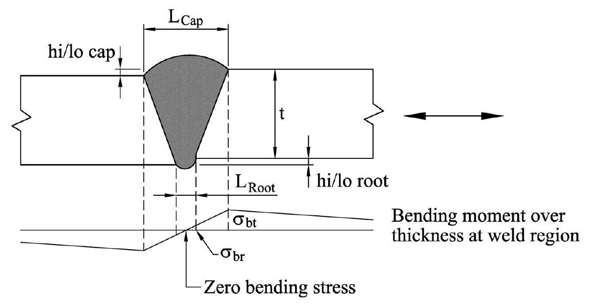 | |
| Figure 2-16 Stress distribution due to axial misalignment at single-sided welds in tubular members | |
| """ | |
| # create the openai client | |
| # YOU WILL NEED AN OPENAI KEY - PUT IT BELOW AND DO NOT SAVE THIS ONLINE!!!!! | |
| import openai | |
| client = openai.OpenAI( | |
| # defaults to os.environ.get("OPENAI_API_KEY") | |
| api_key="sk-YOUR_API_KEY", | |
| ) | |
| # create the openai api call function | |
| def call_openai(prompt: str, model: str, response_model, system_prompt: str, temperature: float): | |
| completion = client.chat.completions.create( | |
| model=model, | |
| temperature=temperature, | |
| functions=[response_model.openai_schema], | |
| messages=[ | |
| {"role": "system", "content": system_prompt}, | |
| {"role": "user", "content": prompt} | |
| ], | |
| ) | |
| return completion | |
| # specify the model | |
| model = "gpt-4-1106-preview" | |
| # give the name of the standard so that it can be included in the schema | |
| standard = "DNV-RP-C203 Fatigue design of offshore steel structures. Recommended practice" | |
| system_prompt = f"Please process the standard clause using `EngineeringStandardClause`. This standard is {standard}" | |
| # call the function | |
| completion = call_openai(prompt, model, EngineeringStandardClause, system_prompt, 0.0) | |
| # print json object to console | |
| arguments = json.loads(json.dumps(completion.choices[0].message.function_call.arguments)) | |
| print(arguments) | |
| # your output should look like this: | |
| """ | |
| { | |
| "name": "DNV-RP-C203", | |
| "description": "Fatigue design of offshore steel structures. Recommended practice", | |
| "clause_name": "Stresses at girth welds in seam welded pipes and S-N data", | |
| "section": "2.10.1", | |
| "equations": [ | |
| { | |
| "expression": "SCF = 1 + \\frac{3 \\delta_m}{t} e^{-\\sqrt{t / D}}", | |
| "description": "Stress concentration factor for weld root due to maximum allowable eccentricity.", | |
| "output_variable": { | |
| "name": "SCF", | |
| "description": "Stress Concentration Factor" | |
| }, | |
| "variables": [ | |
| { | |
| "name": "\\delta_m", | |
| "description": "Maximum allowable eccentricity" | |
| }, | |
| { | |
| "name": "t", | |
| "description": "Wall thickness" | |
| }, | |
| { | |
| "name": "D", | |
| "description": "Pipe diameter" | |
| } | |
| ] | |
| }, | |
| { | |
| "expression": "\\sigma_{bt} = \\frac{3 \\delta_m}{t} e^{-\\sqrt{t / D}} \\sigma_m", | |
| "description": "Local bending stress at the weld toe due to axial misalignment and membrane stress.", | |
| "output_variable": { | |
| "name": "\\sigma_{bt}", | |
| "description": "Local bending stress at the weld toe" | |
| }, | |
| "variables": [ | |
| { | |
| "name": "\\delta_m", | |
| "description": "Axial misalignment" | |
| }, | |
| { | |
| "name": "t", | |
| "description": "Wall thickness" | |
| }, | |
| { | |
| "name": "D", | |
| "description": "Pipe diameter" | |
| }, | |
| { | |
| "name": "\\sigma_m", | |
| "description": "Membrane stress" | |
| } | |
| ] | |
| }, | |
| { | |
| "expression": "\\sigma_{br} = \\frac{3 \\delta_m L_{Root}}{t L_{Cap}} e^{-\\sqrt{t / D}} \\sigma_m", | |
| "description": "Bending stress in the pipe wall at the transition from the weld to the base material at the root.", | |
| "output_variable": { | |
| "name": "\\sigma_{br}", | |
| "description": "Bending stress at the weld root" | |
| }, | |
| "variables": [ | |
| { | |
| "name": "\\delta_m", | |
| "description": "Axial misalignment" | |
| }, | |
| { | |
| "name": "L_{Root}", | |
| "description": "Width of the weld at the root" | |
| }, | |
| { | |
| "name": "t", | |
| "description": "Wall thickness" | |
| }, | |
| { | |
| "name": "L_{Cap}", | |
| "description": "Width of the weld at the cap" | |
| }, | |
| { | |
| "name": "D", | |
| "description": "Pipe diameter" | |
| }, | |
| { | |
| "name": "\\sigma_m", | |
| "description": "Membrane stress" | |
| } | |
| ] | |
| }, | |
| { | |
| "expression": "SCF_{Root} = 1 + \\frac{3 \\delta_m L_{Root}}{t L_{Cap}} e^{-\\sqrt{t / D}} = 1 + (SCF_{Cap} - 1) \\frac{L_{Root}}{L_{Cap}}", | |
| "description": "Stress concentration factor for the weld root including the effect of axial misalignment.", | |
| "output_variable": { | |
| "name": "SCF_{Root}", | |
| "description": "Stress Concentration Factor for the weld root" | |
| }, | |
| "variables": [ | |
| { | |
| "name": "SCF_{Cap}", | |
| "description": "Stress concentration factor for the weld cap" | |
| }, | |
| { | |
| "name": "\\delta_m", | |
| "description": "Axial misalignment" | |
| }, | |
| { | |
| "name": "L_{Root}", | |
| "description": "Width of the weld at the root" | |
| }, | |
| { | |
| "name": "t", | |
| "description": "Wall thickness" | |
| }, | |
| { | |
| "name": "L_{Cap}", | |
| "description": "Width of the weld at the cap" | |
| }, | |
| { | |
| "name": "D", | |
| "description": "Pipe diameter" | |
| } | |
| ] | |
| } | |
| ], | |
| "tables": [ | |
| { | |
| "name": "Table 2-5", | |
| "caption": "Classification of welds in pipelines", | |
| "table": "| Description | Tolerance requirement (mean hi/lo-value) | $S-N$ curve | Thickness exponent $k$ | $SCF$ |\n| --- | --- | --- | --- | --- |\n| Single side (Hot spot) | | D | 0.15 | Eq. (2.10.1) |\n| Single side | $\\delta_m \\leq 1.0 mm$ | E | 0.00 | Eq. (2.10.4) |\n| Single side | $1.0 mm < \\delta_m \\leq 2.0 mm$ | F | 0.00 | |\n| Single side (Hot spot) | $2.0 mm < \\delta_m \\leq 3.0 mm$ | F1 | 0.00 | |\n| Double side | | D | 0.15 | Eq. (2.10.1) |\n| Ground weld (outside and inside) | | C | 0.00 | Eq. (2.10.1) for outside and Eq. (2.10.4) for inside |" | |
| } | |
| ], | |
| "figures": [ | |
| { | |
| "name": "Figure 2-16", | |
| "caption": "Stress distribution due to axial misalignment at single-sided welds in tubular members", | |
| "figure": "" | |
| } | |
| ], | |
| "internal_reference": { | |
| "reference": "App.A", | |
| "name": "DNVGL-ST-F101", | |
| "section": "Appendix A" | |
| }, | |
| "external_reference": "None" | |
| } | |
| """ |
Sign up for free
to join this conversation on GitHub.
Already have an account?
Sign in to comment