This text is documented in AsciiDoc format
Suggested viewer FireFox plugin Asciidoctor.js Live Preview
Scilab Serial Communication Toolbox (SSCT) is inspired by
a toolbox with a same name
originally developed by
Aditya Sengupta and
Enrico Segre. However,
this new development line is an
attempt to comply / resemble MATLAB serial communication functionalities
and syntax, as much as possible. The toolbox adds serial port
(e.g. RS-232) protocol communication to Scilab / Scicoslab platforms,
which are Free and Open Source Software (FOSS) alternatives of MATLAB.
The toolbox can be used for sending commands to control robots, motors,
or reading sensors such as GPS, laser scanners, compasses, etc [Esposito2009].
For the moment the toolbox only works on Wondows OS,
but development for Linux and macOS are under progress and will be added soon.
This toolbox is still in early stage prototyping stage and functions are not compiled.
To use it just download this Gist and run the ssctmain.sci in Scilab.
For ScicosLab, due to the fact that multiline commenting /* … */ is yet to be implemented,
the AsciiDoc documentations in those tags need to be removed in advance.
A serial object structure with similar
properties
/ attributes and
functions
of the one in MATLAB has been developed. There are of course some syntax
differences due to Scilab intrinsic limitations, not-implemented
features, as well as extra features considered to improve upon what
MathWorks has already done. Considering that Scilab doesn’t have
built-in Serial Port communication, external languages including Tcl,
PowerShell, CMD / batch, bash, C, C++ have been used. Moreover, due to the
lack of object oriented programing (OOP) capability in Scilab there are major
differences between this toolbox and MATLAB. Mainly the serial object
has no routine / subroutine / procedure accessible through dot .
operator, as seen in the OOP languages. Furthermore, all the MATLAB
functions starting with an f are changed to s to avoid confusion and
conflicts with other Scilab functions, as well as possible copyright issues.
For example MATLAB’s fopen is sopen in this toolbox. The syntax has been changed in a way to be more consistent and concise.
Although there are other FOSS options like Python, Octave, Julia, Sage, Maxima, R and FreeMat …, Scilab stands out among these options for having the great xcos / scicos environment, which is a replica of SIMULINK visual programing. xcos / scicos can also include code blocks from other languages such as C/C++, Fortran, Scilab, and Modelica language. In addition, Scilab / ScicosLab also have a nice GUI building functionality which resembles MATLAB syntax. In general for users coming from a MATLAB background it is one of the best alternatives.
A typical serial port communication session has five steps:
-
Find the valid, available, open, defined serial ports using the
slistfunction -
Create a serial port object using the
sdefinefunction, specifying the required properties. -
Opening the port using the
sopenfunction and adjusting the properties usingsconfigandsinfofunction -
Sending or receiving data using
-
sputfor putting data to the serial port buffer andsflushfor sending them out -
sgetfunction for taking data out of the serial port buffer
-
-
Closing the port using the
sclosefunction and cleaning up theDefinedPortslist using thesdeletefunction.
Alternatively one can use the sprint and sread functions to send and
read data in one step.
s1 = sdefine(Port = "COM1", BaudRate = 4800);
sopen(s1);
sput(s1, "*IDN?");
out = sget(s1);
sclose(s1);
sdelete(s1);
clear s1;
or alternatively using the simpler syntax:
sprint(Port = "COM1", Message = "*IDN?", BaudRate = 4800);
sread("COM1"); // to be implementedwrites text to the serial devoice (similar to the MATLAB fprintf)
The SerialPort is a serial port object defined by the serial
function or a string of a valid serial port such as COM1. The
Message is a Scilab string which can be a formatted text created by
Scilab’s msprintf function or a SCPI / SCI command known to the serial
device.
In this example (inspired by this tutorial) you will learn how to communicate with an Arduino microcontroller (MCU) expansion board and a Windows PC, through serial port. By the end of this example you will be able to read the value of a potentiometer, while this can be also expanded to reading any other sensors as well. To follow along the example you require the hardware including an Arduino Uno MCU development board, a potentiometer, wiring and breadboard.
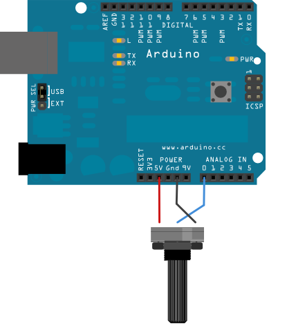
Alternatively you can use SimulIDE to simulate the hardware and the Null-modem emulator (com0com) one Windows, to stablish a pair of virtual serial ports.
The Arduino code is:
int potPin = A0;

long val = 0;
long val_ = 0;

void setup() {
  Serial.begin(9600);
}

void loop() {

    val = ((long) analogRead(potPin));

    if (val != val_) {
      val_ = val;
      Serial.println(val);
    }

}
find the port connected to the Arduino board by running the command:
slist(Verbose = %t, PortList = "all")This will show you are the serial ports recognized by the operating
system, including the "available" and "open"`s. Under `Description
you should be able to find the Arduino serial port.
Scilab code
SimulIDE model
Click to see the source code
link:ex01.simu[role=include]
Result:

For those who are not familiar with serial communication, some terms used in the practice can be difficult to grasp. In this section we will try to explain those terms.
-
message: a serial message is 1 byte or 8 bits, which is able to represent between 0-255.
-
terminator: indicates how a message should end. The common terminator is a carriage return indicated as
"cr"in this toolbox. -
buffer: is like a container on the on both sides of the communication ports. The sender stores the data there before flushing them through the port and the receiver stores them there before dumping them over to the users space. The buffers have limited size which if exceeds the oldest data will be discarded. The size of buffer can be set through
InputBufferSizeandOutputBufferSizeserial object property, which can not exceed the maximum provided by the hardwareMaxInputBufferSizeandMaxOutputBufferSize. If you do not flush/read the data on the sender/receiver side in time it can lead to irreversible data loss. -
checksum: in simple terms is basically a signature attached to each message, known by the receiver, which can be used to verify that the data is not garbled.
-
polling and streaming: when requesting one single measurements from a sensor, it is called polling. If we read data from the sensor given a certain frequency it is called streaming.
-
Serial Command Interface (SCI): firstly used by Motorola in the 1970s, is basically a language known by the serial device (e.g. MCU) to do certain things upon receiving certain messages.
-
serial peripheral interface ( SPI )
-
universal asynchronous receiver/transmitter (UART)
-
USART
-
Standard Commands for Programmable Instruments (SCPI)
-
Transistor–transistor logic (TTL)
-
TTY: teletypewriter, teletype, terminal
-
Serial Port Profile (SPP)
-
EIA Electronic Industries Alliance
-
ANSI American National Standards Institute
-
TIA Telecommunications Industry Association
-
DIN Deutsches Institut für Normung
-
RS Recommended Standard
-
232
-
DTE Data Terminal Equipment eg. IBM computer, printer, plotter etc
-
DCE Data Communication/circuit-terminating Equipment eg. modem, multiplexors, etc
-
-
422, 449, 485, 530
-
-
ASCII: American Standard Code for Information Interchange
Connectors used to be in the form of D-sub series or Mini-DIN
Serial and Parallel ports were found in two different forms, DB-25 and DE-9 (which is mistakenly also referred to as DB-9).
port (e.g. , DB-25, DE-9 …),voltage (TTL 5V, True RS-232 12V), communication standards (RS-232, USB), data transmission method (parallel or serial)
| DE-9 | DB-25 | acronym / abbreviation | Name | typical purpose | DTE | DCE |
|---|---|---|---|---|---|---|
1 |
8 |
DCD |
Data Carrier Detect |
DCE is receiving a carrier from a remote DCE |
in |
out |
2 |
3 |
RxD |
Received Data |
Carries data from DCE to DTE |
in |
out |
3 |
2 |
TxD |
Transmit Data |
Carries data from DTE to DCE |
out |
in |
4 |
20 |
DTR |
Data Terminal Ready |
DTE is ready to receive, initiate, or continue a call |
out |
in |
5 |
7 |
GND |
Common Ground |
Zero voltage reference (signal ground) |
- |
- |
6 |
6 |
DSR |
Data Set Ready |
DCE is ready to receive and send data |
in |
out |
7 |
4 |
RTR |
Ready To Receive |
DTE is ready to receive data from DCE |
out |
in |
7 |
4 |
RTS |
Request To Send |
flow control, DTE requests the DCE prepare to transmit data |
out |
in |
8 |
5 |
CTS |
Clear To Send |
DCE is ready to accept data from the DTE |
in |
out |
9 |
22 |
RI |
Ring Indicator |
DCE has detected an incoming ring signal on the telephone line |
in |
out |
1 |
PG |
Protective Ground |
Frame / Chassis Ground |
- |
- |
|
9 |
||||||
10 |
||||||
11 |
||||||
12 |
SDCD |
Secondary Carrier Detect |
Tone from a modem |
in |
out |
|
13 |
SCTS |
Secondary Clear To Send |
in |
out |
||
14 |
STD |
Secondary Transmitted Data |
out |
in |
||
15 |
ST |
Send Timing |
||||
16 |
SRD |
Secondary Received Data |
in |
out |
||
17 |
RT |
receive timing |
||||
18 |
Loopback |
|||||
19 |
SRTS |
Secondary Request To Send |
out |
in |
||
21 |
Loopback |
|||||
23 |
Signal rate selection |
|||||
24 |
TT |
Transmitter Timing |
||||
25 |
-
[Esposito2009] Joel M. Esposito, Tutorial: Serial Communication in Matlab, 2009, URL


I'm having trouble with launching the .sci files with errors like in the ssctmain.sci
/*
!--error 2
Invalid factor.
at line 2 of exec file called by :