- Tiny AVR programmer: https://www.sparkfun.com/products/11801
- Soldering iron
- (optional, but recommended) Wire strippers
- Solder
- Hook-up wire
- ATTiny85: https://www.sparkfun.com/products/9378
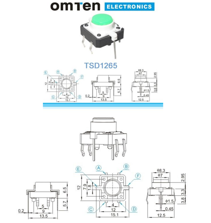
- LED Tactile button, red: https://www.sparkfun.com/products/10442
- 12mm Coin Cell Breakout Board: https://www.adafruit.com/product/1868
- 12mm coin cell: https://www.sparkfun.com/products/337
- 100Ω resistors: https://www.sparkfun.com/products/13761
- 10kΩ resistors: https://www.sparkfun.com/products/14491
- Install Arduino IDE - https://www.arduino.cc/en/Main/Software
- Install USBTinyISP drivers - https://cdn.sparkfun.com/datasheets/Dev/AVR/usbtinyisp_libusb_1.2.6.0.zip
- Install ATTiny board definitions - http://highlowtech.org/?p=1695
- Open
button.inoin Arduino IDE - Insert ATTiny85 into Tiny AVR programmer
- Click "Upload" button, or Sketch/Upload
Note: I'm a flake. When in doubt, follow the schematic.
- Find a good place for the parts in your wand/sword/whatever
- Wire a positive battery terminal ATTiny's VCC
- Wire a negative terminal to ATTiny's GND
- Solder-tie a short lead on the button to the long lead on the button not marked with '+', then wire the bundle to GND
- Wire the other short lead on the same side of the button to ATTiny pin 5 (PB0, bottom-right), and to a 10kΩ resistor
- Wire the other side of the resistor to the positive battery terminal
- Wire the long lead marked '+' to one side of the 100Ω resistor
- Wire the resistor to ATTiny pin 6 (PB1, just above pin 5)
- ATTiny85 Datasheet: https://www.mouser.com/ds/2/268/Atmel-2586-AVR-8-bit-Microcontroller-ATtiny25-ATti-1066528.pdf
- LED Pushbutton

Notes:
button.inoline19.