Created
February 18, 2023 16:26
-
-
Save Lukelectro/907dfeec3a6217beafbbd1636f66cee1 to your computer and use it in GitHub Desktop.
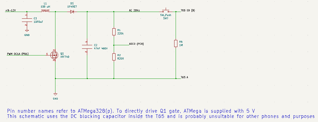
Atmega328p-based DC-AC converter to ring a T65 phone, simpler hardware, but horrible waveshape
This file contains bidirectional Unicode text that may be interpreted or compiled differently than what appears below. To review, open the file in an editor that reveals hidden Unicode characters.
Learn more about bidirectional Unicode characters
| #include <avr/io.h> | |
| #include <avr/interrupt.h> | |
| #define F_CPU 8e6 | |
| #include <util/delay.h> | |
| /* | |
| FUSES = { | |
| .low = 0xE2, //INTRC 8 MHZ, no CKDIV8 | |
| .high = 0xD9, // geen bootloader | |
| .extended = 0xFF, // geen BOD | |
| }; | |
| LOCKBITS = 0xFF; // {LB=PROG_VER_DISABLED, BLB0=LPM_SPM_DISABLE, BLB1=LPM_SPM_DISABLE} | |
| */ | |
| int16_t setpoint = 128; //With 1.1V internal ADC reference and a 8 bit result, 128 means 0.55 V approximately for the output divider | |
| const uint8_t sinus[64]={127,139,152,164,176,187,198,208,217,226,233,239,245,249,252,254,255,254,252,249,245,239,233,226,217,208,198, | |
| 187,176,164,152,139,127,115,102,90,78,67,56,46,37,28,21,15,9,5,2,0,0,0,2,5,9,15,21,28,37,46,56,67,78,90,102,115}; | |
| void setup() | |
| { | |
| /*GPIO*/ | |
| DDRC = 0xBE; // PC0 input, PC6=reset input, rest ouput | |
| DDRB = 0x3F; // all output, except crystal input PB6,7 | |
| DDRD = 0xF7; // all output, except PD3 (switch?) | |
| /* Timer 1, for PWM output and ADC samplerate (PWM /8) | |
| * Has to be set to inverted output, because otherwise OCRA1 == 0 results in a small spike | |
| * on inverted, OCR1A == TOP == ICR1 means a constantly low signal and OCR1A = 0 a nearly constantly high signal | |
| */ | |
| ICR1 = 80; // use 80 as top, so 8M/80=100 kHz PWM | |
| TCCR1A = 0b11000010; // use OC1A output (inverted), fast PWM, ICR1 as top | |
| TCCR1B = 0b00011001; // WGM mode fast PWM ICR1 as top, clock timer from clkIO unprescaled, start | |
| TIMSK1 = (1<<TOIE0); // enable interrupt on overflow (at ICR1 value) | |
| /*ADC*/ | |
| ADMUX = 0b11100000; // set reference voltage to 1V1 internal, use ADC0 as input, left adjust result (so only higher 8 bits have to be read) | |
| ADCSRA = (1<<ADEN)|(1<<ADIE)|(1<<ADPS2)|(1<<ADPS0); // ADC enable, interrupt enable, clock source clkio/32 (8M/32 < 200kHz) | |
| DIDR0 = 0x01; // disable digital input buffer on ADC0 input | |
| sei(); // enable interrupts | |
| } | |
| int main(void) { | |
| uint8_t i=0; | |
| /* */ | |
| setup(); | |
| while (1) { | |
| i++; | |
| if(i>63) i=0; | |
| setpoint = sinus[i]; | |
| _delay_us(257); // TODO: tune to get 20 Hz | |
| } | |
| } | |
| ISR(TIMER1_OVF_vect){ | |
| static uint8_t i=0; | |
| i++; | |
| if(i>=7){ | |
| ADCSRA |= (1<<ADSC); // start a new adc conversion every 8th OVF. OVF at 100 kHz, ADC max is 15ksps at max resolution | |
| i=0; | |
| } | |
| PIND = 0x01; // toggle PD0 for debug | |
| } | |
| ISR(ADC_vect){ | |
| /* | |
| * read adc result, and set new PWM value | |
| * because PWM is inverted to prevent the 1 cycle high output | |
| * 80 means output LOW, 0 means 100% dutycycle high, | |
| * 23 means 70% dutycycle high. | |
| * | |
| * If PWM where not inverted an OCR1A 0 would mean 0 output instead of | |
| * a thin needle of 1 clk cycle, then this would be a bit simpler: | |
| * if error > 0 {if error<56 OCR=error }else ocr=56 else ocr = 0; | |
| */ | |
| uint8_t adcresult = ADCH; | |
| int16_t error = (setpoint - adcresult)*8; // P factor | |
| if(error>0){ | |
| if(error < 57) OCR1A = 80-error; else OCR1A = 40; // limit to 50% dutycycle (40) max | |
| }else OCR1A = 80; | |
| } |
Author
Lukelectro
commented
Feb 18, 2023
Sign up for free
to join this conversation on GitHub.
Already have an account?
Sign in to comment