Reference:
https://wiki.luckfox.com/zh/Luckfox-Pico/Luckfox-Pico-GPIO
My USB to UART Cabe


adb devices
adb -s ${id} shellReference:
https://wiki.luckfox.com/zh/Luckfox-Pico/Luckfox-Pico-GPIO
My USB to UART Cabe
adb devices
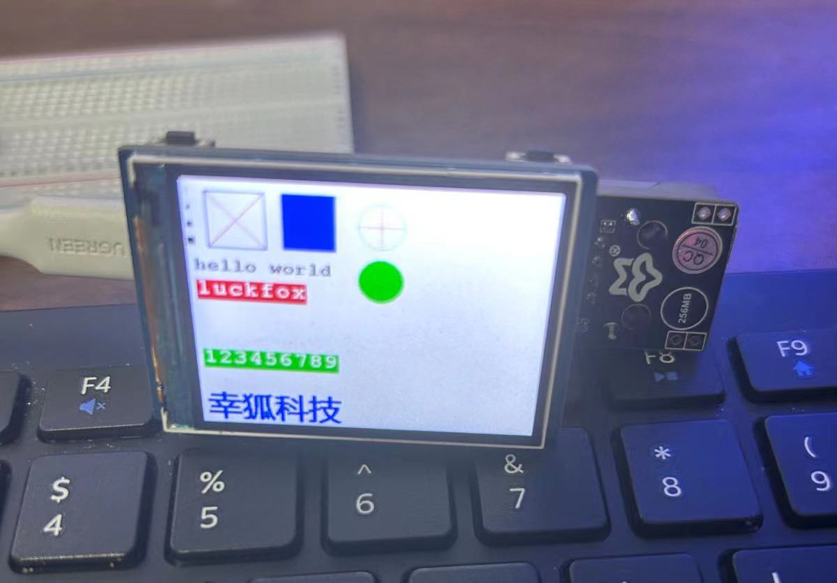
adb -s ${id} shellSPI LCD Demo
Reference:https://wiki.luckfox.com/zh/Luckfox-Pico/Luckfox-Pico-LCD

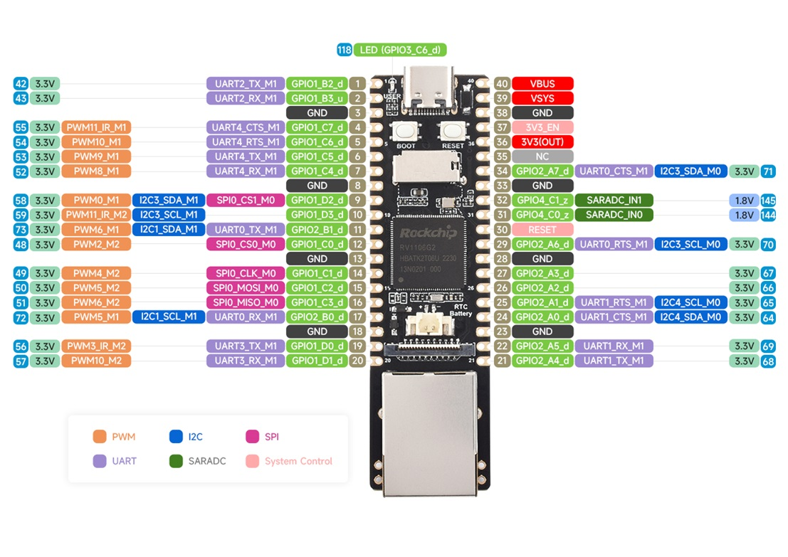
Compare Pico LCD 2's GPIO Layout & LuckFox Pico's,The GPIOs used are:
BL  - 72 - GPIO2-PB0
RST - 51 - GPIO1-PC3
DIN - 50 - GPIO1-PC2
CLK - 49 - GPIO1-PC1
CS  - 48 - GPIO1-PC0
DC  - 73 - GPIO2-PB1
// SPDX-License-Identifier: (GPL-2.0+ OR MIT)
/*
 * Copyright (c) 2022 Rockchip Electronics Co., Ltd.
 */

/dts-v1/;

#include "rv1106.dtsi"
#include "rv1106-evb.dtsi"
#include "rv1106-luckfox-pico-pro-max-ipc.dtsi"

/ {
	model = "Luckfox Pico Max";
	compatible = "rockchip,rv1103g-38x38-ipc-v10", "rockchip,rv1106";
};

/**********GPIO**********/

/{
    /*KEY*/
	gpio2pa5:gpio2pa5 {
		compatible = "regulator-fixed";
		pinctrl-names = "default";
		pinctrl-0 = <&gpio2_pa5>;
		regulator-name = "gpio2_pa5";
		regulator-always-on;
	};

	gpio1pc6:gpio1pc6 {
		compatible = "regulator-fixed";
		pinctrl-names = "default";
		pinctrl-0 = <&gpio1_pc6>;
		regulator-name = "gpio1_pc6";
		regulator-always-on;
	};

	gpio1pc7:gpio1pc7 {
		compatible = "regulator-fixed";
		pinctrl-names = "default";
		pinctrl-0 = <&gpio1_pc7>;
		regulator-name = "gpio1_pc7";
		regulator-always-on;
	};

	gpio1pd1:gpio1pd1 {
		compatible = "regulator-fixed";
		pinctrl-names = "default";
		pinctrl-0 = <&gpio1_pd1>;
		regulator-name = "gpio1_pd1";
		regulator-always-on;
	};

    /*RESET*/
	gpio1pc3:gpio1pc3 {
		compatible = "regulator-fixed";
		pinctrl-names = "default";
		pinctrl-0 = <&gpio1_pc3>;
		regulator-name = "gpio1_pc3";
		regulator-always-on;
	};

	/*BL*/
	gpio2pb0:gpio2pb0 {
		compatible = "regulator-fixed";
		pinctrl-names = "default";
		pinctrl-0 = <&gpio2_pb0>;
		regulator-name = "gpio2_pb0";
		regulator-always-on;
	};
};

&pinctrl {

	/*KEY*/
	gpio2-pa5 {
		gpio2_pa5:gpio2-pa5 {
			rockchip,pins =	<2 RK_PA5 RK_FUNC_GPIO &pcfg_pull_up>;
		};
	};

	gpio1-pc6 {
		gpio1_pc6:gpio1-pc6 {
			rockchip,pins =	<1 RK_PC6 RK_FUNC_GPIO &pcfg_pull_up>;
		};
	};

	gpio1-pc7 {
		gpio1_pc7:gpio1-pc7 {
			rockchip,pins =	<1 RK_PC7 RK_FUNC_GPIO &pcfg_pull_up>;
		};
	};

	gpio1-pd1 {
		gpio1_pd1:gpio1-pd1 {
			rockchip,pins =	<1 RK_PD1 RK_FUNC_GPIO &pcfg_pull_up>;
		};
	};

    /*RESET*/
	gpio1-pc3 {
		gpio1_pc3:gpio1-pc3 {
			rockchip,pins =	<1 RK_PC3 RK_FUNC_GPIO &pcfg_pull_none>;
		};
	};

	/*BL*/
	gpio2-pb0 {
		gpio2_pb0:gpio2-pb0 {
			rockchip,pins =	<2 RK_PB0 RK_FUNC_GPIO &pcfg_pull_none>;
		};
	};
};

/**********FLASH**********/
&sfc {
	status = "okay";
	flash@0 {
		compatible = "spi-nand";
		reg = <0>;
		spi-max-frequency = <75000000>;
		spi-rx-bus-width = <4>;
		spi-tx-bus-width = <1>;
	};

};

/**********SDMMC**********/
&sdmmc {
    max-frequency = <50000000>;
    no-sdio;
    no-mmc;
    bus-width = <4>;
    cap-mmc-highspeed;
    cap-sd-highspeed;
    disable-wp;
    pinctrl-names = "default";
    pinctrl-0 = <&sdmmc0_clk &sdmmc0_cmd &sdmmc0_det &sdmmc0_bus4>;
    status = "okay";
};

/**********SDIO**********/
// &sdio {
// 	max-frequency = <50000000>;
// 	no-sdio;
// 	no-mmc;
// 	bus-width = <4>;
// 	cap-mmc-highspeed;
// 	cap-sd-highspeed;
// 	disable-wp;
// 	pinctrl-names = "default";
// 	pinctrl-0 = <&sdmmc1m0_cmd &sdmmc1m0_clk &sdmmc1m0_bus4 &clk_32k>;
// 	status = "okay";
// };

/**********ETH**********/
&gmac {
	status = "okay";
};

/**********USB**********/
&usbdrd_dwc3 {
	status = "okay";
	dr_mode = "peripheral";
};

/**********I2C**********/
// &i2c1 {
// 	status = "okay";
// 	pinctrl-0 = <&i2c1m1_xfer>;
// 	clock-frequency = <100000>;
// };
&i2c3 {
	status = "okay";
	pinctrl-0 = <&i2c3m1_xfer>;
	clock-frequency = <100000>;
};

// /**********SPI**********/
&spi0 {
	status = "okay";
	pinctrl-names = "default";
	pinctrl-0 = <&spi0m0_pins>;
	cs-gpios = <&gpio1 RK_PC0 1>;
	// cs-gpios = <&gpio1 26 1>;
	#address-cells = <1>;
	#size-cells = <0>;
	spidev@0 {
		compatible = "rockchip,spidev";
		spi-max-frequency = <1000000000>;
		reg = <0>;
	};
};

&pinctrl {
    spi0 {
        /omit-if-no-ref/
        spi0m0_pins: spi0m0-pins {
            rockchip,pins =
                /* spi0_clk_m0 */
                <1 RK_PC1 4 &pcfg_pull_none>,
                /* spie_miso_m0 */
                /* <1 RK_PC3 6 &pcfg_pull_none>, */
                /* spi_mosi_m0 */
                <1 RK_PC2 6 &pcfg_pull_none>;
        };
    };
};


/**********UART**********/

// &uart0 {
// 	status = "okay";
// 	pinctrl-names = "default";
// 	pinctrl-0 = <&uart0m1_xfer>;
// };

// &uart1 {
// 	status = "okay";
// 	pinctrl-names = "default";
// 	pinctrl-0 = <&uart1m1_xfer>;
// };

&uart3 {
	status = "okay";
	pinctrl-names = "default";
	pinctrl-0 = <&uart3m1_xfer>;
};
&uart4 {
	status = "okay";
	pinctrl-names = "default";
	pinctrl-0 = <&uart4m1_xfer>;
};


// /**********PWM**********/

// &pwm0 {
// 	status = "okay";
// 	pinctrl-names = "active";
// 	pinctrl-0 = <&pwm0m0_pins>;
// 	// pinctrl-0 = <&pwm0m1_pins>;
// };
// &pwm1 {
// 	status = "okay";
// 	pinctrl-names = "active";
// 	pinctrl-0 = <&pwm1m0_pins>;
// 	// pinctrl-0 = <&pwm1m1_pins>;
// };

//&pwm2 {
//	status = "okay";
//	pinctrl-names = "active";
//	pinctrl-0 = <&pwm2m2_pins>;
//};
//&pwm3 {
//	status = "okay";
//	pinctrl-names = "active";
//	pinctrl-0 = <&pwm3m2_pins>;
//};
//&pwm4 {
//	status = "okay";
//	pinctrl-names = "active";
//	pinctrl-0 = <&pwm4m2_pins>;
//};
&pwm5 {
	status = "okay";
	pinctrl-names = "active";
	pinctrl-0 = <&pwm5m1_pins>;
	// pinctrl-0 = <&pwm5m2_pins>;
};
&pwm6 {
	status = "okay";
	pinctrl-names = "active";
	pinctrl-0 = <&pwm6m1_pins>;
	// pinctrl-0 = <&pwm6m2_pins>;
};
//&pwm7 {
//	status = "okay";
//	pinctrl-names = "active";
//	pinctrl-0 = <&pwm7m2_pins>;
//};
//&pwm8 {
//	status = "okay";
//	pinctrl-names = "active";
//	// pinctrl-0 = <&pwm8m1_pins>;
//	pinctrl-0 = <&pwm8m0_pins>;
//};
//&pwm9 {
//	status = "okay";
//	pinctrl-names = "active";
//	// pinctrl-0 = <&pwm9m1_pins>;
//	pinctrl-0 = <&pwm9m0_pins>;
//};

&pwm10 {
	status = "okay";
	pinctrl-names = "active";
	pinctrl-0 = <&pwm10m1_pins>;
	// pinctrl-0 = <&pwm10m2_pins>;
	// pinctrl-0 = <&pwm10m0_pins>;
};
&pwm11 {
	status = "okay";
	pinctrl-names = "active";
	pinctrl-0 = <&pwm11m1_pins>;
	// pinctrl-0 = <&pwm11m2_pins>;
	// pinctrl-0 = <&pwm11m0_pins>;
};


&rtc {
	status = "okay";
};
Recompile
cd ~/Luckfox-Pico/luckfox-pico
./build.sh clean
./build.sh
Burn the system via SocToolKit
Modify Makefile,
gcc path: <SDK directory\>/tools/linux/toolchain/arm-rockchip830-linux-uclibcgnueabihf/bin/arm-rockchip830-linux-uclibcgnueabihf-gcc
CC=home/luckfox/Luckfox-Pico/luckfox-pico/tools/linux/toolchain/arm-rockchip830-linux-uclibcgnueabihf/bin/arm-rockchip830-linux-uclibcgnueabihf-gcc
DEV_Conig.h in c/lib/Config
for Pico LCD 2inch
| define in code | Printed Name in LCD Board | Pin number |
|---|---|---|
| GET_KEY1 | KEY0 | 57 |
| GET_KEY2 | KEY1 | 69 |
| GET_KEY_UP | KEY2 | 55 |
| GET_KEY_PRESS | KEY3 | 54 |
/*****************************************************************************

* | File      	:   DEV_Config.h

* | Author      :   Luckfox team

* | Function    :   Hardware underlying interface

* | Info        :

*----------------

* |	This version:   V2.0

* | Date        :   2019-07-08

* | Info        :   Basic version

*

******************************************************************************/

#ifndef _DEV_CONFIG_H_

#define _DEV_CONFIG_H_


#include "Debug.h"


#define USE_DEV_LIB 1


#ifdef USE_DEV_LIB

    #include "sysfs_gpio.h"

    #include "dev_hardware_SPI.h"

	#include <stdio.h>

	#include <unistd.h>

	#include <stdlib.h>

	#include <pthread.h>

	// #define USE_DEV_LIB_PWM

#endif

#include <unistd.h>


#include <errno.h>

#include <stdio.h>

#include <string.h>

#include <stdint.h>


/**

 * data

**/

#define UBYTE   uint8_t

#define UWORD   uint16_t

#define UDOUBLE uint32_t


// #define LCD_DC   (34)

// #define LCD_CS   (48)

// #define LCD_RST  (51)

// #define LCD_BL   (4)


#define LCD_DC   (73)

#define LCD_CS   (48)

#define LCD_RST  (51)

#define LCD_BL   (72)


//LCD

#define LCD_CS_0		DEV_Digital_Write(LCD_CS,0)

#define LCD_CS_1		DEV_Digital_Write(LCD_CS,1)


#define LCD_RST_0		DEV_Digital_Write(LCD_RST,0)

#define LCD_RST_1		DEV_Digital_Write(LCD_RST,1)


#define LCD_DC_0		DEV_Digital_Write(LCD_DC,0)

#define LCD_DC_1		DEV_Digital_Write(LCD_DC,1)


#define LCD_BL_0		DEV_Digital_Write(LCD_BL,0)

#define LCD_BL_1		DEV_Digital_Write(LCD_BL,1)


/*PICO*/

// #define KEY_UP_PIN      55

// #define KEY_DOWN_PIN    134

// #define KEY_LEFT_PIN    137

// #define KEY_RIGHT_PIN   131

// #define KEY_PRESS_PIN   54

// #define KEY1_PIN        57

// #define KEY2_PIN        136

// #define KEY3_PIN        16

// #define KEYA_PIN        57

// #define KEYB_PIN        136

// #define KEYX_PIN        130

// #define KEYY_PIN        132


/*PLUS*/

#define KEY_UP_PIN      55

#define KEY_DOWN_PIN    101

#define KEY_LEFT_PIN    102

#define KEY_RIGHT_PIN   98

#define KEY_PRESS_PIN   54

#define KEY1_PIN        57

#define KEY2_PIN        69 //103

#define KEY3_PIN        16

#define KEYA_PIN        57

#define KEYB_PIN        103

#define KEYX_PIN        100

#define KEYY_PIN        99


#define GET_KEY_UP       		DEV_Digital_Read(KEY_UP_PIN) //

#define GET_KEY_DOWN     		DEV_Digital_Read(KEY_DOWN_PIN)

#define GET_KEY_LEFT     		DEV_Digital_Read(KEY_LEFT_PIN)

#define GET_KEY_RIGHT    		DEV_Digital_Read(KEY_RIGHT_PIN)

#define GET_KEY_PRESS    		DEV_Digital_Read(KEY_PRESS_PIN) //

#define GET_KEY1         		DEV_Digital_Read(KEY1_PIN) //

#define GET_KEY2         		DEV_Digital_Read(KEY2_PIN) //

#define GET_KEY3         		DEV_Digital_Read(KEY3_PIN)

#define GET_KEYA         		DEV_Digital_Read(KEYA_PIN)

#define GET_KEYB         		DEV_Digital_Read(KEYB_PIN)

#define GET_KEYX         		DEV_Digital_Read(KEYX_PIN)

#define GET_KEYY         		DEV_Digital_Read(KEYY_PIN)


#define LCD_SetBacklight(Value) DEV_SetBacklight(Value)


/*------------------------------------------------------------------------------------------------------*/

UBYTE DEV_ModuleInit(void);

void DEV_ModuleExit(void);


void DEV_GPIO_Mode(UWORD Pin, UWORD Mode);

void DEV_Digital_Write(UWORD Pin, UBYTE Value);

UBYTE DEV_Digital_Read(UWORD Pin);

void DEV_Delay_ms(UDOUBLE xms);


void DEV_SPI_WriteByte(UBYTE Value);

void DEV_SPI_Write_nByte(uint8_t *pData, uint32_t Len);

void DEV_SetBacklight(UWORD Value);

#endif
Compile the code:
make clean
make
Copy main file to LuckFox Pico Max
adb -s <device id> push <src> <dest>
adb -s <device id> shell
cd <dest>
chmod 777 main
./main <LCD inch number>
SDK Environmenthttps://wiki.luckfox.com/zh/Luckfox-Pico/Core3566-SDK
sudo ./VBoxLinuxAdditions.run