- Waterfall
- Unified Process
- Agile
The Unified Process lifecycle divides a project into four phases:
- Inception: Establish the scope of the system, including a good understanding of what system to build, by reaching a high-level understanding of the requirements. Mitigate many of the business risks and produce the business case for building the system and a vision document to get buy-in from all stakeholders on whether or not to proceed with the project.
- Elaboration: Reduce major risks to enable cost and schedule estimates to be updated and to get buy-in from key stakeholders. Mitigate major technical risks by taking care of many of the most technically difficult tasks. Design, implement, test, and baseline an executable architecture, including subsystems, their interfaces, key components, and architectural mechanisms such as how to deal with inter-process communication or persistency. Address major business risks by defining, designing, implementing, and testing key capabilities, which are validated with the customer. Do not define and analyze all requirements at this time, as doing so would lead to waterfall development. Detail and analyze only the requirements required to address the above risks.
- Construction: Undertake a majority of the implementation as you move from an executable architecture to the first operational version of your system. Deploy several internal and alpha releases to ensure that the system is usable and addresses user needs. End the phase by deploying a fully functional beta version of the system, including installation and supporting documentation and training material
- Transition: Ensure that software addresses the needs of its users by testing the product in preparation for release and making minor adjustments based on user feedback. At this point in the lifecycle, user feedback focuses mainly on fine-tuning, configuration, installation, and usability issues; all the major structural issues should have been worked out much earlier in the project lifecycle.

-
GRASP - General Responsibility Assignment Software Patterns (or Principles)
-
Controller
-
Problem: What first object beyond the UI layer receives and coordinates “controls” a system operation?
-
Solution: Assign the responsibility to an object representing one of these choices:
- Represents the overall “system”, “root object”, device that the software is running within, or a major subsystem (these are all variations of a facade controller)
- Represents a use case scenario within which the system operation occurs (a use case or session controller)
@RestController
public class CustomerOrdersController {
  private IMediator mediator;

  public CustomerOrdersController(IMediator mediator) {
    this.mediator = mediator;
  }

  @PostMapping(path = "{customerId}/orders")
  public Task<IActionResult> addCustomerOrder(Integer customerId) {
    this.mediator.send(new AddCustomerOrderCommand(customerId, request.Products));
    return Created(string.Empty, null);
  }
}

public class AddCustomerOrderCommandHandler implements IRequestHandler<AddCustomerOrderCommand> {
  private ICustomerRepository customerRepository;
  private IProductRepository productRepository;
  private IForeignExchange foreignExchange;

  public AddCustomerOrderCommandHandler(ICustomerRepository customerRepository, IProductRepository productRepository, IForeignExchange foreignExchange) {
    this.customerRepository = customerRepository;
    this.productRepository = productRepository;
    this.foreignExchange = foreignExchange;
  }

  public Task<Unit> Handle(AddCustomerOrderCommand request, CancellationToken cancellationToken)
  {
    // handling...
  }
}
-
-
Creator
-
Problem: Who creates object A?
-
Solution: Assign class B the responsibility to create object A if one of these is true (more is better)
- B contains or compositely aggregates A
- B records A
- B closely uses A
- B has the initializing data for A
public class Customer extends Entity {
  private List<Order> orders;
  public void addOrder(List<OrderProduct> orderProducts) {
    Order order = new Order(orderProducts); // Creator
    if (this.orders.Count(x => x.IsOrderedToday()) >= 2)  {
        throw new BusinessRuleValidationException("You cannot order more than 2 orders on the same day");
    }
    this.orders.add(order);
    this.addDomainEvent(new OrderAddedEvent(order));
  }
}
As you can see above Customer class compositely aggregates Orders (there is no Order without Customer), records Orders, closely uses Orders and has initializing data passed by method parameters. Ideal candidate for “Order Creator”.
-
-
Indirection
- Problem: Where to assign a responsibility to avoid direct coupling between two or more things?
- Solution: Assign the responsibility to an intermediate object to mediate between other components or services so that they are not directly coupled.
- This is where Mediator Pattern comes in to play. Instead of direct coupling:
public class CustomerOrdersController extends Controller {
  private IOrdersService ordersService;

  public CustomerOrdersController(IOrdersService ordersService) {
    this.ordersService = ordersService;
  }
}
- we can use the mediator object and mediate between objects:
@RestController
public class CustomerOrdersController  {
private IMediator _mediator;

  public CustomerOrdersController(IMediator mediator) {
    this._mediator = mediator;
  }

  @PostMapping(path = "{customerId}/orders")
  public async Task<IActionResult> AddCustomerOrder(Guid customerId,  CustomerOrderRequest request) {
    await _mediator.Send(new AddCustomerOrderCommand(customerId, request.Products));

    return Created(string.Empty, null);
  }
}
-
Information expert
- Problem: What is a basic principle by which to assign responsibilities to objects?
- Solution: Assign a responsibility to the class that has the information needed to fulfill it.
  public class Customer extends Entity {
    private readonly List<Order> orders;
    public GetOrdersTotal(Guid orderId) {
      return this.orders.Sum(x => x.Value);
    }
  }
In the above example Customer class has references to all customer Orders so it is natural candidate to take responsibility of calculating total value of orders
-
Low coupling
- Problem: How to reduce the impact of change? How to support low dependency and increased reuse?
- Solution: Assign responsibilities so that (unnecessary) coupling remains low. Use this principle to evaluate alternatives.
- Coupling is a measure how one element is related to another. The higher the coupling, the greater the dependence of one element to the another.
- Low coupling means our objects are more independent and isolated.
-
High cohesion
- Problem: How to keep objects focused, understandable, manageable and as a side effect support Low Coupling?
- Solution: Assign a responsibility so that cohesion remains high. Use this to evaluate alternatives.
- Cohesion is a measure how strongly all responsibilities of the element are related. In other words, what is the degree to which the parts inside a element belong together.
-
Polymorphism
- Problem: How handle alternatives based on type?
- Solution: When related alternatives or behaviors vary by type (class), assign responsibility for the behavior (using polymorphic operations) to the types for which the behavior varies.
- Polymorphism is fundamental principle of Object-Oriented Design. In this context, principle is strongly connected with (among others) Strategy Pattern.
-
Protected variations
- Problem: How to design objects, subsystems and systems so that the variations or instability in these elements does not have an undesirable impact on other elements?
- Solution: Identify points of predicted variation or instability, assign responsibilities to create a stable interface around them.
-
Pure fabrication
- Problem: What object should have the responsibility, when you do not want to violate High Cohesion and Low Coupling but solutions offered by other principles are not appropriate?>
- Solution: Assign a highly cohesive set of responsibilities to an artificial or convenience class that does not represent a problem domain concept.
public interface IForeignExchange {
    List<ConversionRate> GetConversionRates();
}

public class ForeignExchange implements IForeignExchange {
    private ICacheStore _cacheStore;

    public ForeignExchange(ICacheStore cacheStore) {
        _cacheStore = cacheStore;
    }

    public List<ConversionRate> GetConversionRates() {
        RatesCache ratesCache = this._cacheStore.Get(new ConversionRatesCacheKey());
        if (ratesCache != null) {
            return ratesCache.Rates;
        }
        List<ConversionRate> rates = getConversionRatesFromExternalApi();
        this._cacheStore.Add(new ConversionRatesCache(rates), new ConversionRatesCacheKey(), DateTime.Now.Date.AddDays(1));
        return rates;
    }

    private static List<ConversionRate> getConversionRatesFromExternalApi() {
        // Communication with external API. Here is only mock.
        List conversionRates = new ArrayList<ConversionRate>();
        conversionRates.Add(new ConversionRate("USD", "EUR", (decimal)0.88));
        conversionRates.Add(new ConversionRate("EUR", "USD", (decimal)1.13));
        return conversionRates;
    }
}
-
-
SOLID
- Single responsibility
- A class should have one, and only one, reason to change
- Smaller classes and smaller methods will give you more flexibility, and you don’t have to write much extra code (if any) to do it!
- Open/Close
- Software entities (classes, modules, methods) should be open for extension but closed for modification.
- Liskov Substitution
- Functions that use references to base classes must be able to use objects of derived classes without knowing it.
- Interface Segregation
- Clients should not be forced to depend on interfaces that they do not use.
- Dependency Inversion
- High level modules should not depend on low level modules. Both should depend on abstractions.
- Abstractions should not depend on details. Details should depend on abstractions.
- Single responsibility
- Modelling language to draw diagrams in unified / Standardized way
- Object Oriented Analysis is an investigation of the problem (rather than how a solution is defined)
- During OO analysis, there is an emphasis on finding and describing the objects on the problem domain
- It shows interaction among actors (External Parties) and use Cases (Modules) of the System
- This is a behavioral diagram
- This is not a Data flow Diagram
A sample Use Case Diagram of the Point of Sale system in a shopping mall

- Use Cases is detailing of the Use Case Diagram (UCD)
- Use Cases are textual Artifacts
- Use Case depicts functional requirements primarily
Use cases may be written in 3 forms:
- Brief: One-Paragraph summary, usually of the main success scenario
- Casual: Informal paragraph format
- Fully Dresses: Elaborate. All steps and variations are written in detail
Example of Fully-Dressed Use Case
- Use case UC1: Purchase
- Primary Actor: Cashier
- Stakeholders and Interests:
- Cashier: Want accurate and fast entry, no payment errors
- Salesperson: Wants sales commissions updated properly
- Preconditions: Cashier is identified and authenticated
- Success Guarantee:
- Bill is generated and tax is calculated properly
- Main success scenario:
- The customer arrives at a POS checkout with items to purchase
- The cashier records the ID for item. If there is more than one of the same item, the cashier can enter the quantity as well
- The system determines the item price and adds teh item information to the running sales transaction. The description and the price of the current item are presented.
- On completion of item entry, the cashier indicates to the POS system that item entry is complete
- The system calculates and presents the sale total
- The cashier tells teh customer the total
- The customer give sa cash payment possibly greater than the sale total
- Extensions: (Error Handling / Fall back)
- 2a. If sticker is tampered, enter item ID manually
- 2b. If invalid identifier entered, indicate error
- 7a. If customer did'nt have enough cash, cancel sales transaction.
- * If power failure, restart the transaction
- Special Requirements: Touch screen, User experience, 500 users, ...
- Open issues: What are the tax law variations
- Essential
- Focus is on intend
- Concrete
- UI decisions are embedded in the use case text
- Functional Requirements
- Features and Capabilities
- Functionalities requested by the Customers / Clients
- Non-Functional Requirements
- Usability
- Reliability
- Performance
- Supportability
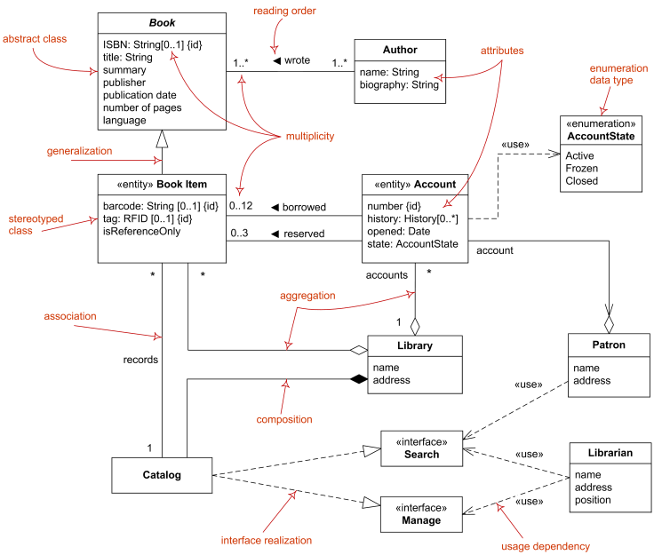
- A Domain Model illustrates meaningful concepts in a problem domain
- Domain models are also called conceptual models, domain object models, and analysis object models.
- It is a representation of real-world things, not software components
- It is a set of static structure diagrams; no operations are defined
- It may show
- Concepts
- Associations between concepts
- Attributes of concepts
- Fully dressed use-case should be created before starting with the domain model
- This is developed during the requirement phase, not the design phase
- Domain concepts are nouns or noun phrases
- Noun phrases which are attributes cannot be domain concepts
- An Association is a relationship between Domain Concepts that indicates some meaningful and interesting connection
- The relationship is always bidirectional
- Name an association based on the TypeName-VerbPhrase-TypeName format
- Association name should start with a Capital Letter. Space to be replaced by hyphen
- Default direction to read an association is Left - Right or from Top - Bottom
- Multiple associations between two domain concepts is possible
- A reflexive association is an association from a class to itself.
- There are two main types:
- Symmetric: There is no logical difference in the semantics of each association end.
- Asymmetric: The ends of the association are semantically different from each other, even though the associated class is the same. Examples include parent-child, supervisor-subordinate and predecessor-successor.
- Multiplicity defines how many instances of type A can be associated with one instance of type B, at a particular moment in time
- An attribute is a logical data value of an object
- Keep attributes simple
- Avoid complex domain concept
- Use pure data values like Number,Date, Boolean, String
- Domain Model is base for designer to create Class Diagram
- Not necessary that all domain concepts will be carried forward
- More implementation concept can be added by designer in class diagram

- Analyst generate system sequence diagram after UCD and UC are written
- System Behavior is a description of what the system does(Without details on how it does it)
- Request through solid arrow
- Response through dotted arrow

- Operation Contracts are documents that describe system behavior.
- Operations(functions/methods) are integral parts of class
- Should be written for all operations inside System Sequence Diagram
Considering the example of makeNewSale() from System Sequence Diagram
Contract CO1: makeNewSale
Operation: makeNewsale()
Cross Reference: Use Case: Process Sale
Pre-Condition: Cashier is authenticated and logged in
Post-Condition:
  - Sale instance created
  - Sale date and sale time was assigned with System date and time
- Object Oriented Design emphasizes a conceptual solution that fulfils the requirements
- Need to define software objects and how they collaborate to fulfill the requirements.
- Designs are implemented in a programming language
- Object is an instance of Class
- Attributes are properties of the class

- Object interaction within system
- Depicts behavior in the system
- There are two types of interaction diagram:
- Collaboration Diagram
- Sequence Diagram
- Collaboration diagram illustrates object interaction in a graph or network format

- SSD deals with the interaction between external agents vs the system, whereas interaction diagram deals with the object interaction within system
- In SSD, system is a black box

- The Object lifeline shows the extent of the life of an object in the diagram
- Newly created objects are placed at their creation height

- Conditional methods calls are triggered based on a specific condition.
- Conditions specified are called as Guard Conditions
- Eg: In the below sequence diagram, the call to methodB() from classA will be performed only if the value of color is Red. Else, the call will be skipped

- Iterations are indicated by following the sequence number by a asterisk '*'
- It is also possible to add an iteration clause indicating recurrence values

- This is also called as State Chart or a State Machine
- A State Diagram illustrates the events and state of things
- It can be drawn for system, sub-system or an object in the system
An Event is a trigger, or an occurrence
A State is a Condition of an entity at a given moment of time
A Transition is a relation between two states
In the below example, we have an entity Named Telephone. The state diagram depicts different states and of the entity
- Events: Off Hook and On Hook
- State: Idle, Active
- Transition: Shows the relationship between two states through the arrow

- An Activity diagram is a behavioral diagram i.e. it depicts the behavior of a system. An activity diagram portrays the control flow from a start point to a finish point showing the various decision paths that exist while the activity is being executed.
- They Show the flow of activities in a process
- Used to model dynamic aspects of a system

- Specifies alternate paths based on the boolean expression
- Represented by Rhombus
- Swimlane is a way in which the performed activities can be grouped by the same actor on an Activity diagram.
- To use swimlanes in an activity diagram, we need to arrange the activity diagram into vertical zones that are separated by the lines.
-
Creational Design Patterns: Deal with initializing and configuring objects
- Abstract Factory: Allows the creation of objects without specifying their concrete type.
- Builder: Uses to create complex objects.
- Factory Method: Creates objects without specifying the exact class to create.
- Prototype: Creates a new object from an existing object.
- Singleton: Ensures only one instance of an object is created.
-
Structural Design Patterns: Composition of classes or objects. Decouple interface and implementation of classes
- Adapter: Allows for two incompatible classes to work together by wrapping an interface around one of the existing classes.
- Bridge: Decouples an abstraction so two classes can vary independently.
- Composite: Takes a group of objects into a single object.
- Decorator: Allows for an object’s behavior to be extended dynamically at run time.
- Facade: Provides a simple interface to a more complex underlying object.
- Flyweight: Reduces the cost of complex object models.
- Proxy: Provides a placeholder interface to an underlying object to control access, reduce cost, or reduce complexity.
-
Behavior Design Patterns: Deal with dynamic interactions among societies of objects. How they distribute responsibility
- Chain of Responsibility: Delegates commands to a chain of processing objects.
- Command: Creates objects which encapsulate actions and parameters.
- Interpreter: Implements a specialized language.
- Iterator: Accesses the elements of an object sequentially without exposing its underlying representation.
- Mediator: Allows loose coupling between classes by being the only class that has detailed knowledge of their methods.
- Memento: Provides the ability to restore an object to its previous state.
- Observer: Is a publish/subscribe pattern which allows a number of observer objects to see an event.
- State: Allows an object to alter its behavior when its internal state changes.
- Strategy: Allows one of a family of algorithms to be selected on-the-fly at run-time.
- Template Method: Defines the skeleton of an algorithm as an abstract class, allowing its sub-classes to provide concrete behavior.
- Visitor: Separates an algorithm from an object structure by moving the hierarchy of methods into one object.
Click here for Implementations of Gang-of-Four design Patterns in Java
- An Adapter pattern acts as a connector between two incompatible interfaces that otherwise cannot be connected directly.
- An Adapter wraps an existing class with a new interface so that it becomes compatible with the client's interface.
- When an outside component provides captivating functionality that we'd like to reuse, but it's incompatible with our current application. A suitable Adapter can be developed to make them compatible with each other
- When our application is not compatible with the interface that our client is expecting
- When we want to reuse legacy code in our application without making any modification in the original code
- The Factory Pattern is a Creational design pattern and is part of the GoF‘s formal list of design patterns.
- This pattern defines an interface for creating an object, but let subclasses decide which class to instantiate.
- This pattern delegates the responsibility of initializing a class from the client to a particular factory class by creating a type of virtual constructor.

- When the implementation of an interface or an abstract class is expected to change frequently
- When the current implementation cannot comfortably accommodate new change
- When the initialization process is relatively simple, and the constructor only requires a handful of parameters
- The Singleton Pattern is a Creational design pattern and is part of the GoF‘s formal list of design patterns.
- This pattern aims to keep a check on initialization of objects of a particular class by ensuring that only one instance of the object exists throughout the Java Virtual Machine.
- A Singleton class also provides one unique global access point to the object so that each subsequent call to the access point returns only that particular object.
- For resources that are expensive to create (like database connection objects)
- It's good practice keeping all loggers as Singletons which increases performance
- Classes which provide access to configuration settings for the application
- Classes that contain resources that are accessed in shared mode
- The Strategy Pattern is a Behavioral design pattern and is part of the GoF‘s formal list of design patterns.
- The strategy pattern allows us to change the behavior of an algorithm at runtime.
- Typically, we would start with an interface which is used to apply an algorithm, and then implement it multiple times for each possible algorithm.
- The Composite Pattern is a Structural design pattern and is part of the GoF‘s formal list of design patterns.
- The composite pattern is meant to allow treating individual objects and compositions of objects, or "composites" in the same way.
- It can be viewed as a tree structure made up of types that inherit a base type, and it can represent a single part or a whole hierarchy of objects.
- The pattern can be broken down into:
- Component: is the base interface for all the objects in the composition. It should be either an interface or an abstract class with the common methods to manage the child composites.
- Leaf: implements the default behavior of the base component. It doesn't contain a reference to the other objects.
- Composite: has leaf elements. It implements the base component methods and defines the child-related operations.
- Client: has access to the composition elements by using the base component object.
- The Facade Pattern is a Structural design pattern and is part of the GoF's formal list of design patterns.
- A facade encapsulates a complex subsystem behind a simple interface. It hides much of the complexity and makes the subsystem easy to use.
- It decouples a client implementation from the complex subsystem.
- Below is a class diagram representing the facade Pattern:

- The Observer Pattern is a Behavioral design pattern and is part of the GoF's formal list of design patterns.
- This Pattern allows some objects to notify other objects about changes in their state.
- It specifies communication between objects: Observable and Observers.
- An observable is an object which notifies observers about the changes in its state.