Embedded System & Microcontroller Projects: 01 Home Automation system using by RC5 Remote and PIC18F458/8051 microcontroller.
- Project Name : Home Automation System using by RC5 Remote and PIC18F458/8051 microcontroller.
- Skill : IR Remote(Transmitter), IR receiver, programming used Embedded C, Hardware design Multisim, PCB design in Ultiboard, Microcontroller used PIC18F458/P89Vrd2BN.
- Application : In Industry, Home Automation etc.
- Result: Completed.
-
- This project is very useful. My main aim is used this project in home. Generally in our home we used to on/off light or fan etc. a switch now I have developed it by a remote means switch not needed. In this project I have used one remote, IR receiver, RC5 protocol and microcontroller.
IR receiver: In here this IR receiver is used which manufactured by SIEMENS.Usually Philips remote are RC5 compatible.
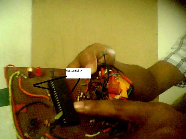
- In here one Philips remote is used because it is RC5 compatible. When we pressed the remote button then IR receiver received a signal and this signal is digital. IR receiver connected with 8051 microcontroller and then microcontroller reads the value from IR receiver. In here the communication rule in between IR receiver and 8051 microcontroller is RC5 protocol. The RC5 code is a 14-bit word bi-phase coded signal. The two first bits are start bits, always having the value one. The next bit is a control bit or toggle bit, which is inverted every time a button is pressed on the remote control transmitter. Five system bits hold the system address so that only the right system responds to the code. Usually, TV sets have the system address 0, VCR’s the address 5 and so on. The command sequence is six bits long, allowing up to 64 different commands per address. The RC5 bit length is approximately 1.8mS. The Code is repeated after every 114 ms.


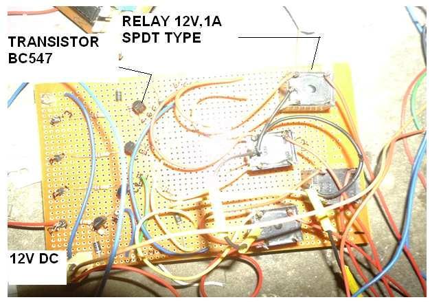
- In program we are assigned this value, suppose when pressed 1 button in remote then microcontroller read the value from IR receiver and if switch condition is matched then operation will continue otherwise it checked other conditions. In this project we used just five pin means control five switch only. In general we control 31 switch using by 8051 microcontroller. At normal condition the microcontroller pin value is set to zero, when we pressed the switch and microcontroller read the value from IR receiver and if condition is matched then pin goes to high means 1. Again we pressed the same button then the pin goes to low. Here transistor BC547 is used for switch. Here snubber circuit used for switching circuit.