I have a 3D printer, as most makers do these days. Specifically, I have a Prusa i3 MK3. Recently, I've been looking into rapid prototyping of PCBs with very tiny components - we're talking stuff like QFN packages, which have a pitch of 0.2mm between leads. The typical toner transfer method won't work on pins these tiny, so I need an alternative approach.
After some digging, I found that a lot of people have had great success in this field by using laser etchers. The game plan is to effectively spray-paint a copper board with flat black, fast-dry enamel paint. Once it's dry, you can use a very tightly-focused high-power laser to selectively vaporize the paint, exposing the copper underneath. This effectively turns the paint into an acid mask, just like toner transfer. After this step you just toss the board into ferric chloride (or your etchant of choice) and the rest of the process is the same as toner transfer. The key is that laser diodes can achieve much higher resolutions than laser printers - especially if you pick up the right one.
To control the whole thing, you need a CNC system of some kind. This is where the 3D printer comes into play. The standard approach is to mount a laser to the extruder, and essentially run the whole etch job with a G-code file - just like you were printing something, but in this case the extruder is off the whole time and the system is just moving the laser around.
Now, to actually drive, the laser, you need a TTL signal that can selectively turn it on and off at the right times. One popular option is to hijack the print fan signal and piggyback the laser on it, so you can control it with M106 (print fan on) and M107 (print fan off). That didn't work for me because Prusa's firmware does some special shenanigans with the print fan PWM signal - they manually control it in software to deal with the tachometer. This is a long topic and I'll write about it more in the future when I stop being lazy.
Anyway, so the print fan is a bust. That means I need to find some other PWM-capable pin that is both accessible in the extension headers, and isn't being used by the printer already. Controlling the pin itself is easy - Marlin (the firmware that Prusa is based off of) comes with a G-code called M42, which literally lets you set the PWM state of arbitrary pins. Long story short, here's the breakdown of all of the PWM pins:
| Pin | Avail? | Location | Timer | Function |
|---|---|---|---|---|
| 2 | Yes | J19 3 | 3B | Power panic (input) |
| 3 | No | Extruder | 3C | Extruder heater (output) |
| 4 | No | Bed | 0B | Bed header (output) |
| 5 | Yes | P2 1 | 3A | Unused? (LCD Backlight strength, who cares) |
| 6 | Yes | Fan 1 | 4A | Print Fan |
| 7 | No | Not connected! | 4B | --- |
| 8 | Yes | Fan 0 | 4C | Extruder Fan |
| 9 | Yes | P1 9 | 2B | LCD Controller Button Click |
| 10 | Yes | Z_MIN | 2A | PINDA |
| 11 | Yes | Y_MIN | 1A | Y_MIN (NOTE: On Timer 1, can't be PWM'd) |
| 12 | Yes | X_MIN | 1B | X_MIN (NOTE: On Timer 1, can't be PWM'd) |
| 13 | No? | LED | 0A / 1C | LED, (NOTE: On Timer 1, can't be PWM'd) |
| 44 | No | None | 5C | Extruder analog reference input |
| 45 | No | None | 5B | Z analog reference input |
| 46 | No | None | 5A | X&Y analog reference input |
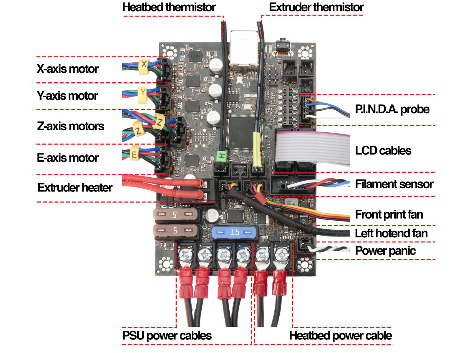
Here's a picture of the board when it's all connected up.
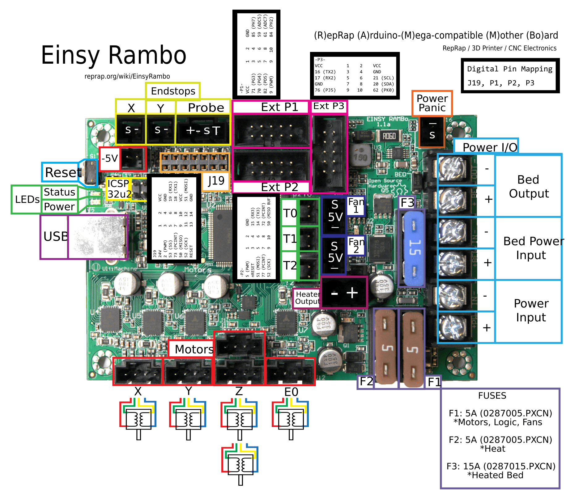
Here's a picture of the pinout on (some of) the headers.
As a quick background, the Atmega 2560 (the CPU that the Prusa board, called the EinsyRambo, uses) has 16 PWM pins. Each pin is connected to a hardware timer that drives the PWM signal. There are 6 timers total, so each one has multiple pins attached to it.
So first things first, pins 3, 4, 7, 13, 44, 45, and 46 are out. They aren't accessible via headers. 7 is actually a perfect candidate for what we want, but it literally isn't connected to the CPU. It's just floating there, disconnected from the world. I'm actually kind of upset about that. Nevertheless, that leaves 2, 5, 6, 8, 9, 10, 11, and 12.
Next, you might see the X and Y endstops aren't used. Luckily, they're connected to PWM pins! That would make them perfect targets for laser control. Unfortunately, they don't work. Marlin reserves timer 1. Any PWM pin you want to use that's attached to timer 1 won't work. The X and Y endstops, pins 11 and 12, are on timer 1. They're out. That leaves 2, 5, 6, 8, 9, and 10.
6 and 8 are connected to the print fan and extruder fan, respectively. There are some major software-based PWM routines in the Prusa firmware for dealing with them, so let's consider them out of bounds unless we have no other choice. That leaves 2, 5, 9, and 10.
9 and 10 are attached to the main control button on the LCD screen and the PINDA probe, respectively. We could rewire them, but again let's save that as a last resort. That leaves 2 and 5.
In the firmware for 3.8.1, pin 5 isn't attached to anything. Physically, it's captured by the LCD connector cables, but in software, it's idle. It's supposed to be a control for the LCD backlight brightness, but it's commented out (on line 102) so as of 3.8.1, it doesn't do anything. It does return in 3.9 though, so it does have some use in newer versions. Anyway, it's on timer 3 so it looks like a great contender.
Pin 2 is physically disconnected and ready to roll. It's #3 on the J19 expansion header. It's also on timer 3, which makes it perfect for this usage. In fact, in my first version, I used this pin and it worked great as far as laser etching goes! However, I noticed a major problem when I actually tried to use the printer for, well, printing something - the extruder and the bed both refused to heat up. After much debugging, I found that pin 2 is actually being used - not in software, but in hardware. Here's the official schematic for the EinsyRambo. If you look through it, you'll see that pin 2 is connected to "nAC_FAULT". Following it along, it feeds into two hardware-based ANDs for the extruder and the print bed - if nAC_FAULT is low, the power to both components is immediately cut. This is actually part of Einsy's "power panic" feature - when the printer detects a loss of AC power in the middle of a print, it goes into a special failsafe mode. The heaters are instantly turned off to save capacitor power, the extruder stops, and the printer records its position. The idea is that when power is restored, the printer can resume from where it left off when power died. It's a really neat feature, but it means that for me to use pin 2 as the laser control, I will lose power panic (since the pin is now an output instead of an input).
All of that being said, it is certainly possible to use pin 2 as the laser control. To do so, though, you really should modify the firmware so it treats the pin as an output only during a laser etching G-code file and reverts it back to an input when the file is complete. If you abort the file, you have to set it manually. It's kind of a pain to deal with. You could just say screw the power panic feature and remove it entirely - it's up to you if that trade-off is worth it.
For me, I ended up going with pin 5. That meant I had to rewire the P2 header with a bunch of jumpers so all other 9 pins were still connected to the LCD, then pin 5 got its own jumper that tied into the laser. It's definitely not the prettiest setup but it does work, and this way I get to keep power panic enabled. In future firmware updates, I'll just have to disable LCD brightness modification. I can live without that.
I suppose if you're really hardcore, you can try to directly solder a wire onto the unused pin 7 of the ATmega. That would guarantee you aren't mucking with the firmware - in fact, you could probably do laser control with the stock firmware, and all subsequent releases, by just running the M42 command with P7 as an argument. This is way beyond my capabilities though, so I'm sticking with pin 5.
I can confirm, that pin 7 is working well if you are brave enough to risk your Einsy
https://forum.prusaprinters.org/forum/postid/486313/
You will need to add an M400 before every M42 to make sure the movement has finished prior executing M42.