Requirements and Resources are available here.
- aliexpress.us/item/3256802762497814.html
- https://www.amazon.com/dp/B087PXTJ78/
- https://store.merifix.com/products/mf300-fixture-kit
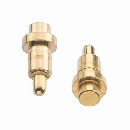
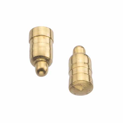
Pogo pins consisting of a plunger (or head), barrel (or body), and a fully encapsulated fine spring, to provide the spring force required to maintain positive contact. All have a high durability, exceeding 10,000 mating cycles.
-
Through hole with stop:
-
SMT:
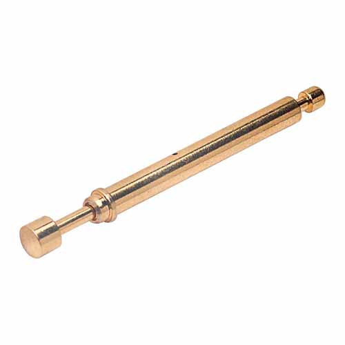
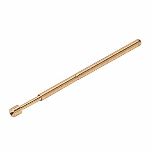
Probes designed for manual test jigs or automated test equipment (ATE), also known as “bed of nails”. Single and two-part styles, with a range of head options. Glue or solder to the equipment bed, and attach test cable to the rear end.
- One part test probe:
Designed to be be connected with wire wrap in a traditional bed of nails.
- Two part test probe:
Functionality identical to one part probes but the top section can be replaced if it wears out or a different contract is needed.
Needs a fixed offset. PCB with pogo pins, laser cut acrylic allowing the DUT to bottom out on the acrylic. Screw the pcb onto the base with the pogos pointing out. This will require the right material thickness and pogo pin length. XY location needs to be aligned sufficiently, mounting holes are the best locator but is inconvenient. Use nylon tapers for compression on areas that don't have parts.
-
Test pin pcb
-
Stop bezel with test pin pcb mounted to it.
-
XY stabilization
- Bezel indexing outline
- Taper pins indexing mounting holes
- Free alignment (terrible idea)
- Pillers as outline
-
DUT compression
- Laser cut with pillers inserted
- Built up laser cuts
- Mounting holes compression (could be combined with XY Stabilization)
- Compressible pad
-
Compression switch for enabling power. This could be turned on with a timer (rc+fet or micro perhaps).
-
Power switch
-
Automode switch (automatically powers up, runs test with compression)
-
Power brick
-
Computer connection
-
We could have some nylon taper + stop pillers made for mounting holes (parameterize the design for other screw sizes). Print with MJF, SLS, or similar.
-
Compress other locations with the through hole sections removed. The through base side will need to have a stop and we may need to shim to avoid bending. Length of pins on long boards is critical.
-
Boards susceptible to bending needs to be compressed only with on board pillars
-
PCB w/ pogo pins
-
Acrylic plate with pogo pin PCB mounted to it
- pogo pins need to be pcb thickness + acylic thickness - compression depth
- SendCutSends thinest acrylic is 3 mm
- 4.6 mm thickness, 5 mm is for through hole is perfect
- Surface mount can use 4.5mm acrylic w/ 5mm pins, could also go with longer compression w/ 4mm pins
-
Second plate mounted to the first with bolts, this should constrain the board outline at a few points. Areas where mousebites are should be cut out.
- Use holes on both for aligning as that is better constrained than the outline
- Could use a 3d printed insert to the base instead for more control over thickness
-
Top plate with platic pins compress the board