Last active
October 2, 2019 20:26
-
-
Save wdevore/3274dec5cfbfbb0b63a2c6a58635d0a0 to your computer and use it in GitHub Desktop.
Simple BCD Counter using a Rotary Encoder and using IceStorm toolchain while targeted at TinyFPGA-B2
This file contains bidirectional Unicode text that may be interpreted or compiled differently than what appears below. To review, open the file in an editor that reveals hidden Unicode characters.
Learn more about bidirectional Unicode characters
| // Rotary Encoder driving a 2 digit 7 Segmented display - top.v | |
| // The BCD decoder is Async. | |
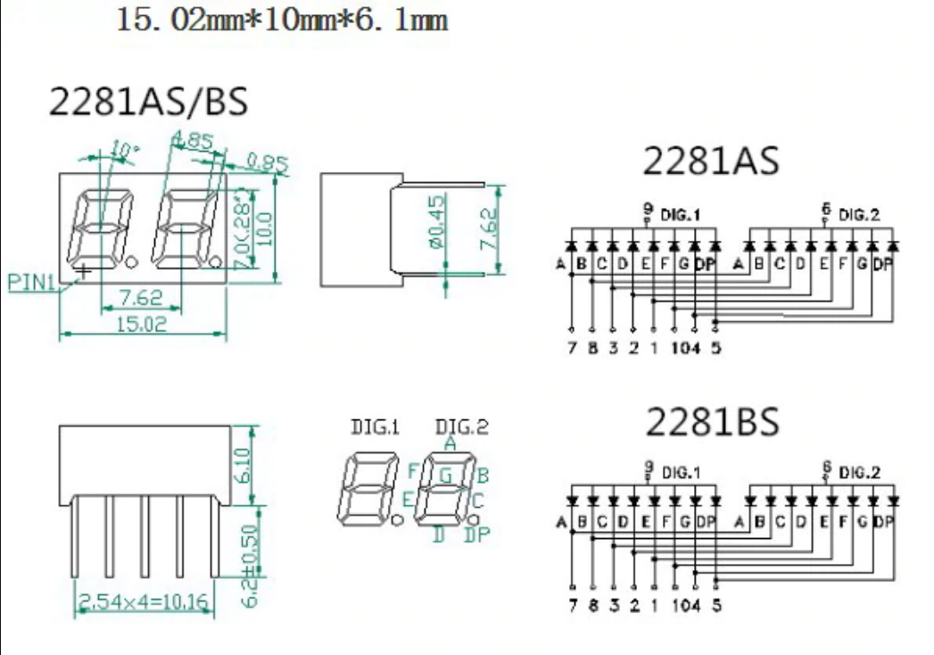
| // The display is a 2281AS which has 2 digits and 2 decimal points | |
| // Pinout: | |
| // 9 = digit 1 common cathode | |
| // 6 = digit 2 common cathode | |
| // 7 = A segment | |
| // 8 = B segment | |
| // 3 = C segment | |
| // 2 = D segment | |
| // 1 = E segment | |
| // 10 = F segment | |
| // 4 = G segment | |
| // 5 = DP segment | |
| // -------------------------------------------------------------------------- | |
| // Sync switch debouncer | |
| // -------------------------------------------------------------------------- | |
| module digital_filter( | |
| input clk, | |
| input D, | |
| output reg Q); | |
| reg[3:0] dfilter4; | |
| localparam valid0 = 4'b0000, valid1 = 4'b1111; | |
| always @(posedge clk) | |
| begin | |
| dfilter4 <= {dfilter4[2:0], D}; | |
| case(dfilter4) | |
| valid0: Q <= 0; | |
| valid1: Q <= 1; | |
| default: Q <= Q; // hold value | |
| endcase | |
| end | |
| endmodule | |
| // -------------------------------------------------------------------------- | |
| // Basic flip flop | |
| // -------------------------------------------------------------------------- | |
| module flip_flop | |
| #( | |
| parameter Default = 0 | |
| ) | |
| ( | |
| input D, | |
| input C, | |
| output Q, | |
| output notQ | |
| ); | |
| reg state; | |
| assign Q = state; | |
| assign notQ = ~state; | |
| always @ (posedge C) begin | |
| state <= D; | |
| end | |
| // Simulation | |
| initial begin | |
| state = Default; | |
| end | |
| endmodule | |
| // -------------------------------------------------------------------------- | |
| // Rotary decoder | |
| // Base on: https://www.fpga4fun.com/QuadratureDecoder.html | |
| // This decoder is sometimes called a "4x decoder" because it counts all | |
| // the transitions of the quadrature inputs. | |
| // Note: I still want to build a variation based on these: | |
| // https://www.fpga4student.com/2017/04/simple-debouncing-verilog-code-for.html | |
| // https://www.beyond-circuits.com/wordpress/tutorial/tutorial12/ | |
| // -------------------------------------------------------------------------- | |
| module quadrature_decoder ( | |
| input A, | |
| input B, | |
| input Clk, | |
| output Dir, | |
| output Shift | |
| ); | |
| wire s0; | |
| wire s1; | |
| wire s2; | |
| wire s3; | |
| wire s4; | |
| wire s5; | |
| flip_flop #( | |
| .Default(0) | |
| ) | |
| DIG_D_FF_1bit_i0 ( | |
| .D( A ), | |
| .C( Clk ), | |
| .Q( s0 ) | |
| ); | |
| flip_flop #( | |
| .Default(0) | |
| ) | |
| DIG_D_FF_1bit_i1 ( | |
| .D( B ), | |
| .C( Clk ), | |
| .Q( s5 ) | |
| ); | |
| flip_flop #( | |
| .Default(0) | |
| ) | |
| DIG_D_FF_1bit_i2 ( | |
| .D( s0 ), | |
| .C( Clk ), | |
| .Q( s1 ) | |
| ); | |
| flip_flop #( | |
| .Default(0) | |
| ) | |
| DIG_D_FF_1bit_i3 ( | |
| .D( s5 ), | |
| .C( Clk ), | |
| .Q( s4 ) | |
| ); | |
| flip_flop #( | |
| .Default(0) | |
| ) | |
| DIG_D_FF_1bit_i4 ( | |
| .D( s1 ), | |
| .C( Clk ), | |
| .Q( s2 ) | |
| ); | |
| flip_flop #( | |
| .Default(0) | |
| ) | |
| DIG_D_FF_1bit_i5 ( | |
| .D( s4 ), | |
| .C( Clk ), | |
| .Q( s3 ) | |
| ); | |
| assign Dir = (s1 ^ s3); | |
| assign Shift = (s1 ^ s2 ^ s4 ^ s3); | |
| endmodule | |
| // Reference: http://verilogcodes.blogspot.com/2015/10/verilog-code-for-8-bit-binary-to-bcd.html | |
| // This handles three digits but this gist only uses 2 digits. | |
| module binary2bcd( | |
| input[7:0] bin, | |
| output[11:0] bcd | |
| ); | |
| //Internal variables | |
| reg[3:0] i; | |
| // The "Double Dabble" algorithm | |
| always @(bin) | |
| begin | |
| bcd = 0; // initialize bcd to zero. | |
| for (i = 0; i < 8; i = i+1) begin // run for 8 iterations | |
| bcd = {bcd[10:0],bin[7-i]}; // concatenation | |
| // if a hex digit of 'bcd' is more than 4, add 3 to it. | |
| if(i < 7 && bcd[3:0] > 4) | |
| bcd[3:0] = bcd[3:0] + 3; | |
| if(i < 7 && bcd[7:4] > 4) | |
| bcd[7:4] = bcd[7:4] + 3; | |
| if(i < 7 && bcd[11:8] > 4) | |
| bcd[11:8] = bcd[11:8] + 3; | |
| end | |
| end | |
| endmodule | |
| // -------------------------------------------------------------------------- | |
| // x4 decoder produces all 4 events from 1 turn of the rotary but we only want | |
| // to recognize only one of them. So this module is a basic 2 bit counter that | |
| // emits true when the counter = 0. | |
| // -------------------------------------------------------------------------- | |
| module event_detect ( | |
| input Clk, | |
| output Detected | |
| ); | |
| wire s0; | |
| wire s1; | |
| wire s2; | |
| wire s3; | |
| flip_flop #( | |
| .Default(0) | |
| ) | |
| DIG_D_FF_1bit_i0 ( | |
| .D( s0 ), | |
| .C( Clk ), | |
| .Q( s1 ), | |
| .notQ ( s0 ) | |
| ); | |
| flip_flop #( | |
| .Default(0) | |
| ) | |
| DIG_D_FF_1bit_i1 ( | |
| .D( s2 ), | |
| .C( s0 ), | |
| .Q( s3 ), | |
| .notQ ( s2 ) | |
| ); | |
| assign Detected = (s1 & s3); | |
| endmodule | |
| // -------------------------------------------------------------------------- | |
| // Main module | |
| // -------------------------------------------------------------------------- | |
| module top ( | |
| output pin1_usb_dp,// USB pull-up enable, set low to disable | |
| output pin2_usb_dn, | |
| input pin3_clk_16mhz, // 16 MHz on-board clock | |
| // pins 13-7 should be connected to Dual digit LED display | |
| // --- Board pins | Segment pins --- | |
| output pin13, // Pin 7 A | |
| output pin12, // Pin 8 B | |
| output pin11, // Pin 3 C | |
| output pin10, // Pin 2 D | |
| output pin9, // Pin 1 E | |
| output pin8, // Pin 10 F | |
| output pin7, // Pin 4 G | |
| // output pin6, // Pin 5 Decimal point (currently unused) | |
| output pin5, // Pin 9 CC Digit #1 (Left most) Active Low <-- relative to Text on display side. | |
| output pin4, // Pin 6 CA Digit #2 (Right most) Active Low | |
| // Rotaty Inputs | |
| input pin14_sdo, // Rotary input A : Yellow before Green = CW | |
| input pin15_sdi // Rotary input B | |
| ); | |
| reg[22:0] clk_1hz_counter = 23'b0; // Hz clock generation counter | |
| reg clk_cyc = 1'b0; // Hz clock | |
| reg[7:0] segment_controls = 0; // 7 Segment control lines | |
| reg[7:0] bin_count = 0; | |
| reg[11:0] bcd; | |
| // This display is a dual digit display which means both digits share the same | |
| // Anodes. This means we need to alternate between each digit using a boolean scanning technique. | |
| reg digit_one_on; | |
| reg digit_two_on; | |
| reg[3:0] digit; | |
| // 2KHz because of the quadrature | |
| localparam FREQUENCY = 23'd2000; | |
| wire inv_A, inv_B; | |
| wire quad_dir; | |
| wire quad_shift; | |
| wire event_enabled; | |
| wire QA; | |
| wire QB; | |
| // Debouncers | |
| digital_filter dfA(.clk(clk_cyc), .D(pin14_sdo), .Q(QA)); | |
| digital_filter dfB(.clk(clk_cyc), .D(pin15_sdi), .Q(QB)); | |
| // Convert from negative logic to positive logic | |
| not(inv_A, QA); | |
| not(inv_B, QB); | |
| // Generate events based on A/B | |
| quadrature_decoder decoder(.A(inv_A), .B(inv_B), .Clk(clk_cyc), .Dir(quad_dir), .Shift(quad_shift)); | |
| // Filter out 3 of the 4 events. We just want one. | |
| event_detect ed(.Clk(quad_shift), .Detected(event_enabled)); | |
| // Decode binary counter to BCD | |
| // Size of the output is 3 digits* 4 bits = 12 bits. But we ignore the upper 4bits. | |
| binary2bcd b2b(.bin(bin_count), .bcd(bcd)); | |
| // Clock divder and generator | |
| always @(posedge pin3_clk_16mhz) begin | |
| if (clk_1hz_counter < 23'd7_999_999) | |
| clk_1hz_counter <= clk_1hz_counter + FREQUENCY; | |
| else begin | |
| clk_1hz_counter <= 23'b0; | |
| clk_cyc <= ~clk_cyc; | |
| end | |
| end | |
| // Warning! You can't use the 16MHz clock because: for one that would introduce cross-domain | |
| // clocking, and two, quadrature is based off of the 2KHz clock so they would be out of sync. | |
| // Introducing a FIFO would be nutty and overkill. | |
| always @(posedge clk_cyc) begin | |
| if (event_enabled == 1 && quad_shift == 1) begin | |
| if (quad_dir == 0) begin | |
| // Going down | |
| if (bin_count > 0) | |
| bin_count <= bin_count - 1; | |
| else | |
| bin_count <= 0; | |
| end | |
| else begin | |
| // Going up | |
| if (bin_count < 8'd99) | |
| bin_count <= bin_count + 1; | |
| else | |
| bin_count <= 8'd99; | |
| end | |
| end | |
| else | |
| bin_count <= bin_count; | |
| // Toggle scan control | |
| if (digit_two_on == 1) begin | |
| digit_one_on <= 1; // Turn on digit #1 | |
| digit_two_on <= 0; | |
| digit <= bcd[3:0]; | |
| end | |
| else begin | |
| digit_one_on <= 0; | |
| digit_two_on <= 1; // Turn on digit #2 | |
| digit <= bcd[7:4]; | |
| end | |
| // Decode digit to 7 segment control pins | |
| case (digit) // ABCDEFGP | |
| 0: segment_controls <= 8'b11111100; | |
| 1: segment_controls <= 8'b01100000; | |
| 2: segment_controls <= 8'b11011010; | |
| 3: segment_controls <= 8'b11110010; | |
| 4: segment_controls <= 8'b01100110; | |
| 5: segment_controls <= 8'b10110110; | |
| 6: segment_controls <= 8'b00111110; | |
| 7: segment_controls <= 8'b11100000; | |
| 8: segment_controls <= 8'b11111110; | |
| 9: segment_controls <= 8'b11100110; | |
| endcase | |
| end | |
| // Route digit control pin, only one is on "Active Low"/negative logic. | |
| assign | |
| pin4 = digit_one_on, | |
| pin5 = digit_two_on; | |
| // Route to segment pins | |
| assign | |
| pin13 = segment_controls[7], | |
| pin12 = segment_controls[6], | |
| pin11 = segment_controls[5], | |
| pin10 = segment_controls[4], | |
| pin9 = segment_controls[3], | |
| pin8 = segment_controls[2], | |
| pin7 = segment_controls[1]; | |
| // pin6 currently unused | |
| // Debug | |
| // assign | |
| // pin18 = quad_dir, | |
| // pin19 = quad_shift; | |
| assign | |
| pin1_usb_dp = 1'b0, | |
| pin2_usb_dn = 1'b0; | |
| endmodule // top |
The circuit. Note: it uses just 2 resistors, but you really should use a resistor for each segment. This circuit uses the "Double Dabble" algorithm.
See rotary_encoder.v for circuit and diagrams.

In Action

Sign up for free
to join this conversation on GitHub.
Already have an account?
Sign in to comment
The circuit uses the 2281AS Common Cathode for positive logic.