After having messed with an unbranded wifi lightbulb and a ENER-J power monitoring smart socket I thought I would have a look at a smart power strip with USB also from the company ENER-J. This particular model didn't have an entry on the Tasmota device templates repository nor was it listed as not compatible so I thought I would take a chance on it being ESP8266 based, since the ENER-J smart socket was there seemed a good chance the power strip would be too.
The power strip is Tuya based and can be flashed with Tuya-Convert for now. Absent any numbering on the power strip I chose to number the sockets starting from where the power enters the strip with the USB sockets last, so socket1 is the one closest to the power cable. The pinout and device template for this power monitoring plug:
- GPIO0 Power button LED
- GPIO3 Socket2 LED
- GPIO4 Socket2 Relay
- GPIO5 Socket3 LED
- GPIO12 Socket1 LED
- GPIO13 Socket1 Relay
- GPIO14 USB Sockets LED + Power
- GPIO15 Socket3 Relay
- GPIO16 Power Button input
{"NAME":"ENER-J SHA5207","GPIO":[544,0,0,321,225,322,1,1,320,224,227,226,32,1],"FLAG":0,"BASE":18}
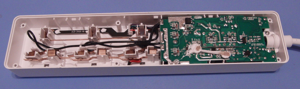


A brief look at the inside of the power strip didnt reveal any obvious pads for serial programming the TYWE3S module, in the above photos I desoldered one of the incoming power cables to get better photos but it might be possible to get to the serial pads on the esp module without any desoldering if you are careful in the event tuya-convert no longer works but it wouldnt be the easiest thing to do.
Tuya-convert worked on the device I purchased in Dec 2020, I have covered the basics of using this in my other gists about converting led lights/plugs, holding the power button puts the power strip in pairing mode.
It wasnt necessary to open the power strip to work out what was connected to what, once it had been flashed with tasmota the first step was to set the first 8 GPIO's (0,1,2,3,4,5,12,13) as relays and see what changes when you toggle them (i used a table lamp to check if a socket was powered or not), then do the same for GPIO's 14,15 and 16. This was enough to identify the LED's and relays, the power button was found by just trying the remaining GPIO's as a button until the correct one was found. There doesnt appear to be a set convention for numbering the sockets so I chose to number them from the power cable with the USB sockets last. The final template for this was:
{"NAME":"ENER-J SHA5207","GPIO":[544,0,0,321,225,322,1,1,320,224,227,226,32,1],"FLAG":0,"BASE":18}