-
-
Save glenpike/971e45d1a586e3baaa45192ea74d1509 to your computer and use it in GitHub Desktop.
| # Raspberry Pi Pico + YM2149 Soundchip test example | |
| # Based on https://github.com/FlorentFlament/ym2149-test | |
| # http://www.ym2149.com/ym2149.pdf | |
| # Pins | |
| # Pico -> YM2149 (DIL) | |
| # GP5 -> CLOCK (22) | |
| # GP6 -> BC1 (29) | |
| # GP7 -> BDIR (27) | |
| # GP8 to GP15 -> DA0 to DA7 (37 to 30) | |
| # VBUS to RESET (23) | |
| # VBUS to BC2 (28) | |
| # VBUS to VCC (40) | |
| from machine import Pin | |
| from rp2 import PIO, StateMachine, asm_pio | |
| import utime | |
| PIO_FREQ = 50000000 #gives us a 20ns cycle time which we can use for delay multipliers | |
| ADDRESS_MODE = 3 | |
| WRITE_MODE = 2 | |
| READ_MODE = 1 #unused | |
| INACTIVE_MODE = 0 | |
| # TODO: Can we combine these 2 functions - the only difference is the control pin values for the mode? | |
| # 8-bit parallel data bus with 2 control pins | |
| # sets the address mode on the bus control pins and writes the supplied data to 8 pins | |
| # cycle time is 1 / PIO_FREQ | |
| # each instruction takes 1 cycle and you can delay for [n] more cycles after each instruction | |
| @asm_pio(sideset_init=PIO.OUT_LOW, out_init=(rp2.PIO.OUT_LOW,) * 8, out_shiftdir=PIO.SHIFT_RIGHT, | |
| autopull=True, pull_thresh=16 ) | |
| def set_address(): | |
| pull() #pull data from the transmit SR | |
| nop() .side(3) #set the mode to address on pins | |
| out(pins, 8) [7] #output data to 8 pins and wait for 7 more cycles | |
| nop() [6] #wait for another 7 cycles (1 instruction + 6) - 300ns total | |
| nop() .side(0) [3] #set mode to inactive for 80ns (1 instruction + 3 cycles) | |
| # 8-bit parallel data bus with 2 control pins | |
| # sets the write mode on the bus control pins and behaves as above | |
| @asm_pio(sideset_init=PIO.OUT_LOW, out_init=(rp2.PIO.OUT_LOW,) * 8, out_shiftdir=PIO.SHIFT_RIGHT, | |
| autopull=True, pull_thresh=16 ) | |
| def set_data(): | |
| pull() #pull data from the transmit SR | |
| nop() .side(2) #set the mode to write on pins | |
| out(pins, 8) [7] #output data to 8 pins and wait for 7 more cycles | |
| nop() [6] #wait for another 7 cycles (1 instruction + 6) - 300ns total | |
| nop() .side(0) [3] #set mode to inactive for 80ns (1 instruction + 3 cycles) | |
| address_sm = StateMachine(0, set_address, freq=PIO_FREQ, sideset_base=Pin(6), out_base=Pin(8)) | |
| data_sm = StateMachine(0, set_data, freq=PIO_FREQ, sideset_base=Pin(6), out_base=Pin(8)) | |
| address_sm.active(1) #Activate address program in first PIO | |
| data_sm.active(2) #Activate address program in second PIO | |
| def send_data(address, data): | |
| address_sm.put(address) | |
| data_sm.put(data) | |
| # 2MHz clock frequency for the YM1249 (affects frequency multiplier for notes) | |
| CLOCK_FREQ = 2000000 | |
| def setup_clock(): | |
| clock = machine.PWM(machine.Pin(5)) | |
| clock.freq(CLOCK_FREQ) | |
| clock.duty_u16(32768) | |
| # Simple C, D, E, F, G, A, B note sequence | |
| note_freqs = [130.81, 146.83, 164.81, 174.61, 196.00, 220.00, 246.94] | |
| # Convert this to values that YM2149 understands | |
| def note_to_data_val(freq): | |
| return int((CLOCK_FREQ / (16 * freq))) | |
| notes = list(map(note_to_data_val, note_freqs)) | |
| setup_clock() | |
| # Initialise registers to 0 | |
| for i in range(16): | |
| send_data(i, 0) | |
| send_data(7, 0xf8) #Mixer setup: Only output clear sound (no noise) | |
| send_data(8, 0x0f) # Volume A - fixed, no envelope | |
| send_data(9, 0x0f) # Volume B - fixed, no envelope | |
| send_data(10, 0x0f) # Volume C - fixed, no envelope | |
| while True: | |
| for i in range(7): | |
| send_data(0, notes[i] & 0xff) | |
| send_data(1, notes[i] >> 8) | |
| send_data(2, notes[i] >> 1 & 0xff) | |
| send_data(3, notes[i] >> 9) | |
| send_data(4, notes[i] >> 2 & 0xff) | |
| send_data(5, notes[i] >> 10) | |
| utime.sleep(0.5) |
Stripped back sideset testing
from machine import Pin
from rp2 import PIO, StateMachine, asm_pio
import utime

PIO_FREQ = 5000 #gives us a 20ms cycle time which we can use for delay multipliers

@asm_pio(sideset_init=PIO.OUT_LOW, out_init=(rp2.PIO.OUT_LOW,) * 8, out_shiftdir=PIO.SHIFT_RIGHT,
 autopull=True, pull_thresh=16 )
def set_address():
    pull()         .side(0x3) [15]
    nop()         .side(0x2)  [15]
    nop()         .side(0x1)  [15]
    nop()         .side(0x0)  [15]


# 8-bit parallel data bus with 2 control pins
# sets the write mode on the bus control pins and behaves as above
@asm_pio(sideset_init=PIO.OUT_LOW, out_init=(rp2.PIO.OUT_LOW,) * 8, out_shiftdir=PIO.SHIFT_RIGHT,
 autopull=True, pull_thresh=16 )
def set_data():
    pull()         .side(0x0) [15]
    nop()         .side(0x1)  [15]
    nop()         .side(0x2)  [15]
    nop()         .side(0x3)  [15]

address_sm = StateMachine(0, set_address, freq=PIO_FREQ, sideset_base=Pin(6), out_base=Pin(8))
data_sm = StateMachine(0, set_data, freq=PIO_FREQ, sideset_base=Pin(6), out_base=Pin(8))

address_sm.active(1)          #Activate address program in first PIO
data_sm.active(2)             #Activate address program in second PIO

while True:
    data_sm.put(0x55)
    utime.sleep(2)
    address_sm.put(0xaa)
utime.sleep(2)Sideset testing - this is outputting a sensible signal on the 2 sideset pins. The possible delay is affected by the number of sideset pins used - there are 5 bits to share between the number of bits for sideset pins and the number of bits to specify delay cycles
from machine import Pin
from rp2 import PIO, StateMachine, asm_pio
import utime

PIO_FREQ = 50000000 #gives us a 2ms cycle time which we can use for delay multipliers

# Simple 2 bit sideset which should count down from 3->0 on pins 6 & 7
@asm_pio(sideset_init=[rp2.PIO.OUT_LOW] * 2, out_init=[rp2.PIO.OUT_LOW] * 8, out_shiftdir=PIO.SHIFT_RIGHT)
def pio_test():
    nop()        .side(0x3) [7] # Maximum delay each cycle is 7 - (5 bits specify sideset pins + delay amount)
    nop()         .side(0x2)  [7] #3.5.1. Side-set https://datasheets.raspberrypi.org/rp2040/rp2040-datasheet.pdf
    nop()         .side(0x1)  [7]
    nop()         .side(0x0)  [7]


test_sm = StateMachine(0, pio_test, freq=PIO_FREQ, sideset_base=Pin(6), out_base=Pin(8))

test_sm.active(1)          #Activate address program in first PIO

while True:
    test_sm.put(0) #We have to put something, but we don't care
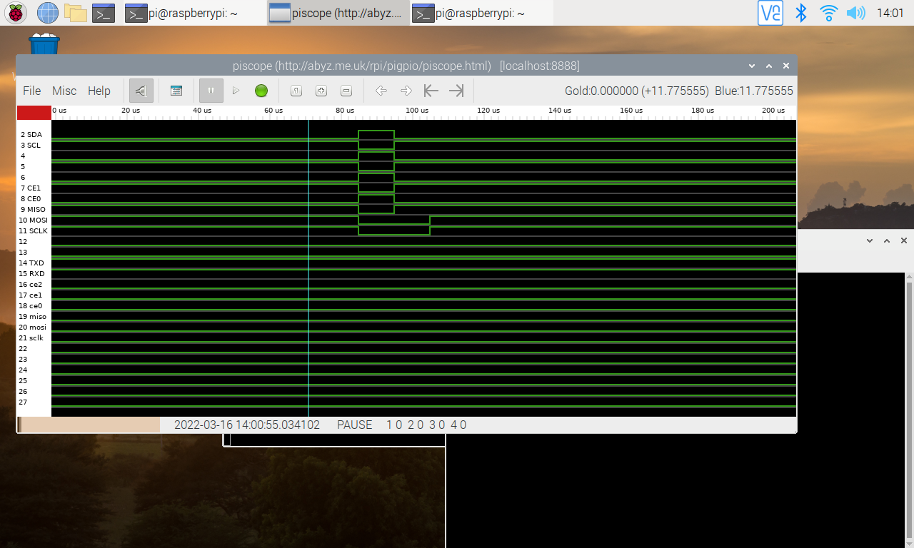
Single PIO function to have 8 bit bus with 2 bit 'sideset' control. To set registers on the YM2149, we set the sideset pins to 'address' mode and write the address byte, then we set the sideset pins to 'data' mode and send the data byte.
We're running the PIO at 5kHz rather than 5MHz so we can see the stuff on PiScope logic analyser.
Also running a 2kHz clock on pin 5
Not sure what's going on with the sideset + delay stuff. Doc's say I should have 5 bytes available for these. As I have 2 sideset pins, I should get 3 bits left for specifying delay right, but I get an error 'delay too large' if I set a delay of [7], so I have to break it down to 2 bit values. Also the addition maybe a bit wonky there as each instruction is a cycle, so delay times can probably be smaller?
from machine import Pin
from rp2 import PIO, StateMachine, asm_pio
import utime

PIO_FREQ = 5000 #gives us a 20ns cycle time which we can use for delay multipliers

@asm_pio(sideset_init=[rp2.PIO.OUT_LOW] * 2, out_init=[rp2.PIO.OUT_LOW] * 8, out_shiftdir=PIO.SHIFT_RIGHT, pull_thresh=16, push_thresh=8 )
def pio_test():
    pull()        .side(0x3)       #set the mode to address on pins
    out(pins, 8)            [1]  #output first byte (address) from FIFO to 8 pins and wait for 7 more cycles
    nop()                   [3]
    nop()                   [3]
    nop()                   [1]  #wait for another 7 cycles (1 instruction + 6) - 300ns total
    nop()                   [3]
    nop()                   [3]
    nop()         .side(0x0)  [3]  #set mode to inactive for 80ns (1 instruction + 3 cycles)
    nop()         .side(0x2)
    out(pins, 8)            [1]  #output second byte (data) from FIFO to 8 pins and wait for 7 more cycles
    nop()                   [3]
    nop()                   [3]
    nop()                   [1]  #wait for another 7 cycles (1 instruction + 6) - 300ns total
    nop()                   [3]
    nop()                   [3]
    nop()         .side(0x0)  [3]  #set mode to inactive for 80ns (1 instruction + 3 cycles)


test_sm = StateMachine(0, pio_test, freq=PIO_FREQ, sideset_base=Pin(6), out_base=Pin(8))

test_sm.active(1)          #Activate address program in first PIO

# 2kHz clock on pin 5
CLOCK_FREQ = 2000

def setup_clock():
    clock = machine.PWM(machine.Pin(5))
    clock.freq(CLOCK_FREQ)
    clock.duty_u16(32768)

setup_clock()

def set_register(address, data):
    test_sm.put((data << 8) | address)

while True:
    set_register(0x55, 0xaa)
    utime.sleep(0.005)
Mimicing setting up the YM2149 and sending a note (~440Hz if the clock was 2MHz)
from machine import Pin
from rp2 import PIO, StateMachine, asm_pio
import utime

PIO_FREQ = 5000 #gives us a 20us cycle time which we can use for delay multipliers

@asm_pio(sideset_init=[rp2.PIO.OUT_LOW] * 2, out_init=[rp2.PIO.OUT_LOW] * 8, out_shiftdir=PIO.SHIFT_RIGHT, pull_thresh=16, push_thresh=8 )
def pio_test():
    pull()        .side(0x3)       #set the mode to address on pins
    out(pins, 8)            [1]  #output first byte (address) from FIFO to 8 pins and wait for 7 more cycles
    nop()                   [3]
    nop()                   [3]
    nop()                   [1]  #wait for another 7 cycles (1 instruction + 6) - 300ns total
    nop()                   [3]
    nop()                   [3]
    nop()         .side(0x0)  [3]  #set mode to inactive for 80ns (1 instruction + 3 cycles)
    nop()         .side(0x2)
    out(pins, 8)            [1]  #output second byte (data) from FIFO to 8 pins and wait for 7 more cycles
    nop()                   [3]
    nop()                   [3]
    nop()                   [1]  #wait for another 7 cycles (1 instruction + 6) - 300ns total
    nop()                   [3]
    nop()                   [3]
    nop()         .side(0x0)  [3]  #set mode to inactive for 80ns (1 instruction + 3 cycles)


test_sm = StateMachine(0, pio_test, freq=PIO_FREQ, sideset_base=Pin(6), out_base=Pin(8))

test_sm.active(1)          #Activate address program in first PIO

# 2kHz clock on pin 5
CLOCK_FREQ = 2000

def setup_clock():
    clock = machine.PWM(machine.Pin(5))
    clock.freq(CLOCK_FREQ)
    clock.duty_u16(32768)

setup_clock()

def set_register(address, data):
    test_sm.put((data << 8) | (address & 0xff))
    utime.sleep(0.005)

for i in range(16):
    set_register(i, 0)

set_register(7, 0xf8) #Mixer setup: Only output clear sound (no noise)
set_register(8, 0x0f) # Volume A - fixed, no envelope
set_register(9, 0x0f) # Volume B - fixed, no envelope
set_register(10, 0x0f) # Volume C - fixed, no envelope

note = 284

while True:
    set_register(0, (note & 0xff))
set_register(1, (note >> 8))Sort of working code - getting some sound out of it, but intermittent. Either timing, or dodgy wiring...
# Raspberry Pi Pico + YM2149 Soundchip test example
# Based on https://github.com/FlorentFlament/ym2149-test

# http://www.ym2149.com/ym2149.pdf
# Pins
# Pico -> YM2149 (DIL)
# GP5  -> CLOCK (22)
# GP6  -> BC1 (29)
# GP7  -> BDIR (27)
# GP8 to GP15 -> DA0 to DA7 (37 to 30)
# VBUS to RESET (23)
# VBUS to BC2 (28)
# VBUS to VCC (40)
from machine import Pin
from rp2 import PIO, StateMachine, asm_pio
import utime

PIO_FREQ = 5000000 #gives us a 20us cycle time which we can use for delay multipliers

@asm_pio(sideset_init=[rp2.PIO.OUT_LOW] * 2, out_init=[rp2.PIO.OUT_LOW] * 8, out_shiftdir=PIO.SHIFT_RIGHT, pull_thresh=16, push_thresh=8 )
def pio_test():
    pull()        .side(0x3)       #set the mode to address on pins
    out(pins, 8)            [1]  #output first byte (address) from FIFO to 8 pins and wait for 7 more cycles
    nop()                   [3]
    nop()                   [3]
    nop()                   [1]  #wait for another 7 cycles (1 instruction + 6) - 300ns total
    nop()                   [3]
    nop()                   [3]
    nop()         .side(0x0)  [3]  #set mode to inactive for 80ns (1 instruction + 3 cycles)
    nop()         .side(0x2)
    out(pins, 8)            [1]  #output second byte (data) from FIFO to 8 pins and wait for 7 more cycles
    nop()                   [3]
    nop()                   [3]
    nop()                   [1]  #wait for another 7 cycles (1 instruction + 6) - 300ns total
    nop()                   [3]
    nop()                   [3]
    nop()         .side(0x0)  [3]  #set mode to inactive for 80ns (1 instruction + 3 cycles)


ym2149_out = StateMachine(0, pio_test, freq=PIO_FREQ, sideset_base=Pin(6), out_base=Pin(8))

ym2149_out.active(1)          #Activate address program in first PIO

# 2kHz clock on pin 5
CLOCK_FREQ = 2000000

def setup_clock():
    clock = machine.PWM(machine.Pin(5))
    clock.freq(CLOCK_FREQ)
    clock.duty_u16(32768)

# Simple C, D, E, F, G, A, B note sequence
note_freqs = [130.81, 146.83, 164.81, 174.61, 196.00, 220.00, 246.94]

# Convert this to values that YM2149 understands
def note_to_data_val(freq):
    return int((CLOCK_FREQ / (16 * (freq * 2))))

notes = list(map(note_to_data_val, note_freqs))

setup_clock()

def set_register(address, data):
    ym2149_out.put((data << 8) | (address & 0xff))
    utime.sleep(0.0005)

for i in range(16):
    set_register(i, 0)

set_register(7, 0xf8) #Mixer setup: Only output clear sound (no noise)
set_register(8, 0x0f) # Volume A - fixed, no envelope
set_register(9, 0x0f) # Volume B - fixed, no envelope
set_register(10, 0x0f) # Volume C - fixed, no envelope

while True:
    for i in range(7):
        note = notes[i]
        set_register(0, (note & 0xff))
        set_register(1, (note >> 8))
        set_register(2, ((note >> 1) & 0xff))
        set_register(3, (note >> 9))
        set_register(4, ((note >> 2) & 0xff))
        set_register(5, (note >> 10))
utime.sleep(0.5)Outputting sound on one channel, but more than one seems to be problematic. Still dodgy wiring. This works - some of the time...
# Raspberry Pi Pico + YM2149 Soundchip test example
# Based on https://github.com/FlorentFlament/ym2149-test

# http://www.ym2149.com/ym2149.pdf
# Pins
# Pico -> YM2149 (DIL)
# GP5  -> CLOCK (22)
# GP6  -> BC1 (29)
# GP7  -> BDIR (27)
# GP8 to GP15 -> DA0 to DA7 (37 to 30)
# VBUS to RESET (23)
# VBUS to BC2 (28)
# VBUS to VCC (40)
from machine import Pin
from rp2 import PIO, StateMachine, asm_pio
import utime

PIO_FREQ = 5000000 #gives us a 20ns cycle time which we can use for delay multipliers

@asm_pio(sideset_init=[rp2.PIO.OUT_LOW] * 2, out_init=[rp2.PIO.OUT_LOW] * 8, out_shiftdir=PIO.SHIFT_RIGHT, pull_thresh=16, push_thresh=8 )
def pio_test():
    pull()        .side(0x3)       #set the mode to address on pins
    out(pins, 8)            [1]  #output first byte (address) from FIFO to 8 pins and wait for 7 more cycles
    nop()                   [3]
    nop()                   [3]
    nop()                   [1]  #wait for another 7 cycles (1 instruction + 6) - 300ns total
    nop()                   [3]
    nop()                   [3]
    nop()         .side(0x0)  [3]  #set mode to inactive for 80ns (1 instruction + 3 cycles)
    nop()         .side(0x2)
    out(pins, 8)            [1]  #output second byte (data) from FIFO to 8 pins and wait for 7 more cycles
    nop()                   [3]
    nop()                   [3]
    nop()                   [1]  #wait for another 7 cycles (1 instruction + 6) - 300ns total
    nop()                   [3]
    nop()                   [3]
    nop()         .side(0x0)  [3]  #set mode to inactive for 80ns (1 instruction + 3 cycles)


ym2149_out = StateMachine(0, pio_test, freq=PIO_FREQ, sideset_base=Pin(6), out_base=Pin(8))

ym2149_out.active(1)          #Activate address program in first PIO

# 2MHz clock on pin 5
CLOCK_FREQ = 2000000

def setup_clock():
    clock = machine.PWM(machine.Pin(5))
    clock.freq(CLOCK_FREQ)
    clock.duty_u16(32768)


# Simple C, D, E, F, G, A, B note sequence
note_freqs = [130.81, 146.83, 164.81, 174.61, 196.00, 220.00, 246.94]

#Take a wild guess
theme = [
[146.83, 0.66],
[146.83, 0.66],
[146.83, 0.66],
[196.00, 4],
[2*146.83, 4],
[294.00, 0.66],
[246.94, 0.66],
[220.00, 0.66],
[2*196.00, 4],
[2*146.83, 2],
[294.00, 0.66],
[246.94, 0.66],
[220.00, 0.66],
[2*196.00, 4],
[2*130.81, 2],
[294.00, 0.66],
[246.94, 0.66],
[294.00, 0.66],
[220.00, 4],
[0, 0.66],
[130.81, 0.66],
[130.81, 0.66]
]

# Convert this to values that YM2149 understands
def note_to_data_val(freq):
    return int((CLOCK_FREQ / (16 * (freq * 2))))

notes = list(map(note_to_data_val, note_freqs))

setup_clock()

def set_register(address, data):
    ym2149_out.put((data << 8) | (address & 0xff))
    utime.sleep(0.005)

for i in range(16):
    set_register(i, 0)

set_register(7, 0xf8) #Mixer setup: Only output clear sound (no noise)
set_register(8, 0x0f) # Volume A - fixed, no envelope
set_register(9, 0x0f) # Volume B - fixed, no envelope
set_register(10, 0x0f) # Volume C - fixed, no envelope

while True:
    for i in range(len(theme)):
        freq_time  = theme[i]
        note = 0
        if freq_time[0] != 0:
            note = note_to_data_val(freq_time[0])
        print("note:  {}: {}".format(note, freq_time))
        set_register(0, (note & 0xff))
        set_register(1, (note >> 8))
        #set_register(2, ((note >> 1) & 0xff))
        #set_register(3, (note >> 9))
        #set_register(4, ((note >> 2) & 0xff))
        #set_register(5, (note >> 10))
utime.sleep(0.25 * freq_time[1])Testing CircuitPython's PIO
import array
import time
import random
import usb_midi
import adafruit_midi

# Raspberry Pi Pico + CircuitPython, testing 8bit bus

# http://www.ym2149.com/ym2149.pdf
# Pins
# Pico -> YM2149 (DIL)
# GP5  -> CLOCK (22)
# GP6  -> BC1 (29)
# GP7  -> BDIR (27)
# GP8 to GP15 -> DA0 to DA7 (37 to 30)
# VBUS to RESET (23)
# VBUS to BC2 (28)
# VBUS to VCC (40)

import board
import rp2pio
import adafruit_pioasm
import pwmio

PIO_FREQ = 5000000 #gives us a 20ns cycle time which we can use for delay multipliers

pio_test = """
.side_set 2
.wrap_target
    pull        side 3       ;set the mode to address on pins
    out pins, 8         [1]  ;output first byte (address) from FIFO to 8 pins and wait for 7 more cycles
    nop                 [3]
    nop                 [3]
    nop                 [1]  ;wait for another 7 cycles (1 instruction + 6) - 300ns total
    nop                 [3]
    nop                 [3]
    nop         side 0  [3]  ;set mode to inactive for 80ns (1 instruction + 3 cycles)
    nop         side 2
    out pins, 8         [1]  ;output second byte (data) from FIFO to 8 pins and wait for 7 more cycles
    nop                 [3]
    nop                 [3]
    nop                 [1]  ;wait for another 7 cycles (1 instruction + 6) - 300ns total
    nop                 [3]
    nop                 [3]
    nop         side 0  [3]  ;set mode to inactive for 80ns (1 instruction + 3 cycles)
.wrap

"""

assembled = adafruit_pioasm.assemble(pio_test)

ym2149_out = rp2pio.StateMachine(
    assembled,
    frequency=PIO_FREQ,
    first_out_pin=board.GP8,
    first_sideset_pin=board.GP6,
    sideset_pin_count=2,
    out_pin_count=8,
    out_shift_right=True,
    pull_threshold=16,
    push_threshold=8
)

# 2MHz clock on pin 5
CLOCK_FREQ = 2000000

def setup_clock():
    clock = pwmio.PWMOut(board.GP5, frequency=CLOCK_FREQ, duty_cycle=32768)

led = pwmio.PWMOut(board.LED, frequency=5000, duty_cycle=32768)

setup_clock()

def set_register(address, data):
    combined = array.array("B", [address, data])
    ym2149_out.write(combined)
    time.sleep(0.005)

while True:
    set_register(0x55, 0xaa)
    time.sleep(0.05)
Output on PiScope - doesn't seem to hold the bus values for the duration as it does above:
O
Above code not yet working. This code writes to my buses okay. Above code appears to be doing things on the bus, but LEDs are lit permanently, so not sure what I'm doing wrong...