Last active
December 1, 2023 02:34
-
-
Save glenpike/971e45d1a586e3baaa45192ea74d1509 to your computer and use it in GitHub Desktop.
# Raspberry Pi Pico + YM2149 Soundchip test example
This file contains bidirectional Unicode text that may be interpreted or compiled differently than what appears below. To review, open the file in an editor that reveals hidden Unicode characters.
Learn more about bidirectional Unicode characters
| # Raspberry Pi Pico + YM2149 Soundchip test example | |
| # Based on https://github.com/FlorentFlament/ym2149-test | |
| # http://www.ym2149.com/ym2149.pdf | |
| # Pins | |
| # Pico -> YM2149 (DIL) | |
| # GP5 -> CLOCK (22) | |
| # GP6 -> BC1 (29) | |
| # GP7 -> BDIR (27) | |
| # GP8 to GP15 -> DA0 to DA7 (37 to 30) | |
| # VBUS to RESET (23) | |
| # VBUS to BC2 (28) | |
| # VBUS to VCC (40) | |
| from machine import Pin | |
| from rp2 import PIO, StateMachine, asm_pio | |
| import utime | |
| PIO_FREQ = 50000000 #gives us a 20ns cycle time which we can use for delay multipliers | |
| ADDRESS_MODE = 3 | |
| WRITE_MODE = 2 | |
| READ_MODE = 1 #unused | |
| INACTIVE_MODE = 0 | |
| # TODO: Can we combine these 2 functions - the only difference is the control pin values for the mode? | |
| # 8-bit parallel data bus with 2 control pins | |
| # sets the address mode on the bus control pins and writes the supplied data to 8 pins | |
| # cycle time is 1 / PIO_FREQ | |
| # each instruction takes 1 cycle and you can delay for [n] more cycles after each instruction | |
| @asm_pio(sideset_init=PIO.OUT_LOW, out_init=(rp2.PIO.OUT_LOW,) * 8, out_shiftdir=PIO.SHIFT_RIGHT, | |
| autopull=True, pull_thresh=16 ) | |
| def set_address(): | |
| pull() #pull data from the transmit SR | |
| nop() .side(3) #set the mode to address on pins | |
| out(pins, 8) [7] #output data to 8 pins and wait for 7 more cycles | |
| nop() [6] #wait for another 7 cycles (1 instruction + 6) - 300ns total | |
| nop() .side(0) [3] #set mode to inactive for 80ns (1 instruction + 3 cycles) | |
| # 8-bit parallel data bus with 2 control pins | |
| # sets the write mode on the bus control pins and behaves as above | |
| @asm_pio(sideset_init=PIO.OUT_LOW, out_init=(rp2.PIO.OUT_LOW,) * 8, out_shiftdir=PIO.SHIFT_RIGHT, | |
| autopull=True, pull_thresh=16 ) | |
| def set_data(): | |
| pull() #pull data from the transmit SR | |
| nop() .side(2) #set the mode to write on pins | |
| out(pins, 8) [7] #output data to 8 pins and wait for 7 more cycles | |
| nop() [6] #wait for another 7 cycles (1 instruction + 6) - 300ns total | |
| nop() .side(0) [3] #set mode to inactive for 80ns (1 instruction + 3 cycles) | |
| address_sm = StateMachine(0, set_address, freq=PIO_FREQ, sideset_base=Pin(6), out_base=Pin(8)) | |
| data_sm = StateMachine(0, set_data, freq=PIO_FREQ, sideset_base=Pin(6), out_base=Pin(8)) | |
| address_sm.active(1) #Activate address program in first PIO | |
| data_sm.active(2) #Activate address program in second PIO | |
| def send_data(address, data): | |
| address_sm.put(address) | |
| data_sm.put(data) | |
| # 2MHz clock frequency for the YM1249 (affects frequency multiplier for notes) | |
| CLOCK_FREQ = 2000000 | |
| def setup_clock(): | |
| clock = machine.PWM(machine.Pin(5)) | |
| clock.freq(CLOCK_FREQ) | |
| clock.duty_u16(32768) | |
| # Simple C, D, E, F, G, A, B note sequence | |
| note_freqs = [130.81, 146.83, 164.81, 174.61, 196.00, 220.00, 246.94] | |
| # Convert this to values that YM2149 understands | |
| def note_to_data_val(freq): | |
| return int((CLOCK_FREQ / (16 * freq))) | |
| notes = list(map(note_to_data_val, note_freqs)) | |
| setup_clock() | |
| # Initialise registers to 0 | |
| for i in range(16): | |
| send_data(i, 0) | |
| send_data(7, 0xf8) #Mixer setup: Only output clear sound (no noise) | |
| send_data(8, 0x0f) # Volume A - fixed, no envelope | |
| send_data(9, 0x0f) # Volume B - fixed, no envelope | |
| send_data(10, 0x0f) # Volume C - fixed, no envelope | |
| while True: | |
| for i in range(7): | |
| send_data(0, notes[i] & 0xff) | |
| send_data(1, notes[i] >> 8) | |
| send_data(2, notes[i] >> 1 & 0xff) | |
| send_data(3, notes[i] >> 9) | |
| send_data(4, notes[i] >> 2 & 0xff) | |
| send_data(5, notes[i] >> 10) | |
| utime.sleep(0.5) |
Sign up for free
to join this conversation on GitHub.
Already have an account?
Sign in to comment
Testing CircuitPython's PIO
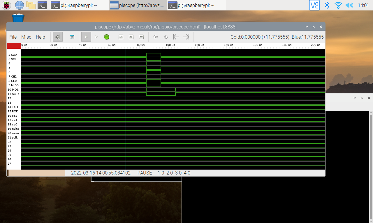
Output on PiScope - doesn't seem to hold the bus values for the duration as it does above:
O