You can see pictures of a robot arm laser engraver attached. Can you figure out what it is engraving?
Note: the flag should be entered all in upper case. It contains underscores but does not contain dashes.
Good luck!
 There are 22 packets of setup, followed by hundreds of packets of
 URB_INTERRUPT out, which contain useful HID data.
The microcontroller doesn't send data to the host, but the host sends (supposedly) instructions to the microcontroller.
Filtering just the host --> 2.3.1 packets and removing the trailing zeros at the end of the HID data results in data looking like this:
5555080301f40101fc08
5555080301dc05021405
5555080301dc0503a406
5555080301dc0504c409
5555080301dc05054006
5555080301dc0506dc05
5555080301f401016009
5555080301e80302dc05
...
Looking at the data, 5555080301 is constant, but the next 5 bytes do change. To figure out how this data affects the servo, we need to find how the packet is constructed.
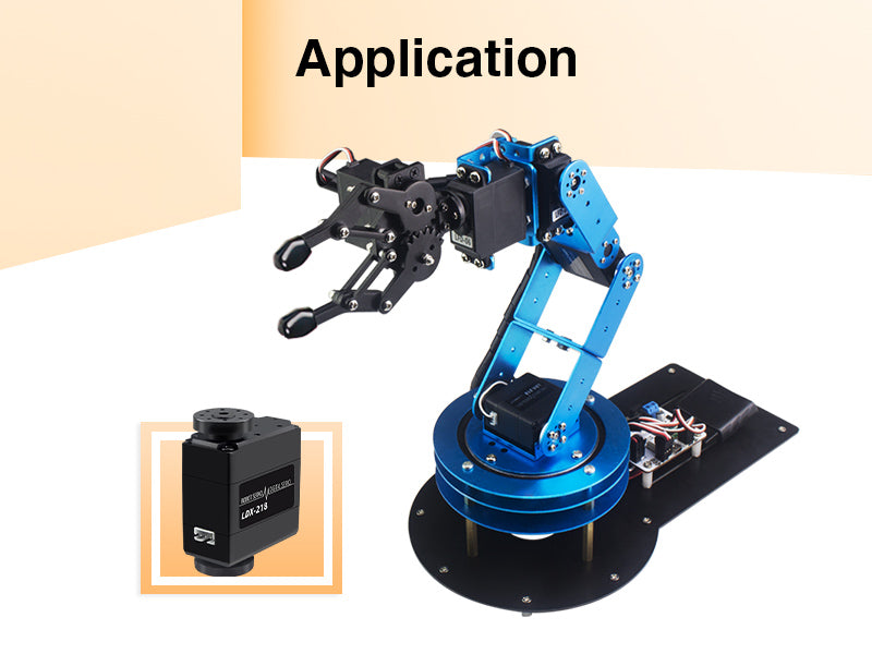
From the lit up image, there are 6 servos visible. They also appear to have a model number LDX-218.
Googling the model number results in this Hiwonder servo, which even references the arm in a picture, but no documentation was found.
Scrolling down a few more results, this website does actually directly list the arm, leading to an Amazon entry, with the title "Robotic Arm Kit 6DOF Programming Robot Arm with Handle PC Software and APP Control with Tutorial" from LewanSoul.

Finally, googling for "LewanSoul Robotic Arm Kit 6DOF github" reveals this repository, which contains information about how the packets are constructed. Success!
Viewing xArmServoController.cpp and xArmServoController.h gives a lot of useful information.
In the header file, there are a few defined constants.

In the c++ file, there is code that sends data to the servo, and reading this code would allow us to determine the structure of the packets.
void xArmServoController::send(int cmd, int len = 0)
{
  serial_port.flush();
  serial_port.write(SIGNATURE);
  serial_port.write(SIGNATURE);
  serial_port.write(len + 2);
  serial_port.write(cmd);
  if (len > 0) {
    serial_port.write(_buffer, len);
  }
}
This function writes the signature twice, followed by the length, and then command. After that comes the buffer. By comparing it to our data,
we do indeed see two 0x55 bytes back to back, followed by 0x08 (len + 2), followed by 0x03 (CMD_SERVO_MOVE), followed by the buffer.
The first byte in our buffered data is 0x01. Scrolling down a bit, we find that the setPosition function sets byte 0 to be 0x01.
void xArmServoController::setPosition(int servo_id, unsigned position, unsigned duration = 1000, bool wait = false)
{
  position = clampServoLimits(servo_id, position);
  _buffer[0] = 1;
  _buffer[1] = lowByte(duration);
  _buffer[2] = highByte(duration);
  _buffer[3] = servo_id;
  _buffer[4] = lowByte(position);
  _buffer[5] = highByte(position);
  send(CMD_SERVO_MOVE, 6);
  if (wait) {
    delay(duration);
  }
}
Now that we know how the packets are created, we can attempt to decode the packets. For the first recovered packet,
55550803 01   f401     01 fc08
HEADER   MOVE DURATION ID POSITION
It's important to note that duration and position are in little-endian order. That means they should actually be 0x01f4 and 0x08fc respectively.
Using a quick Python script to parse the rest, we get the following data:
with open("data.txt", "r") as f:
    for line in f:
        buf = line[8:]
        dur = int(buf[4:6], 16) * 256 + int(buf[2:4], 16)
        sid = int(buf[6:8], 16)
        loc = int(buf[10:12], 16) * 256 + int(buf[8:10], 16)
        print(f'{dur}\t{sid}\t{loc}')
DUR ID POS
500 1 2300
1500 2 1300
1500 3 1700
1500 4 2500
1500 5 1600
1500 6 1500
...
An image online shows which IDs control which servos. ID 1 turns on/off the laser via some physical switch.

In our data, servos 4, 5, and 6 are always moved to the same location, so they can be ignored. That leaves servos 2 and 3 responsible for moving the arm in the x- and y-axes.
Since the first 3 characters drawn must be CTF, we found that:
- Servo 1 turns off the laser if it moves to 2300, on if it moves to 2400
- Servo 2 moves left/right, inverted
- Servo 3 moves up/down
- The canvas uses the range x: [1300, 1500], y: [1500, 1700]
- For some letters like
F, the engraving is split into two parts: one sequence that draws the top and left lines, and a second one to draw the middle dash.

Drawing the rest of the letters, keeping in mind that any dashes are continuations of previous letters, we got the flag.
Flag: CTF{6_D3GREES_OF_FR3EDOM}