These determine the assumed/default size of instruction operands, and restricts which opcodes are available, and how they are used.
Modern operating systems, booted inside Real mode,
must escalate first to Protected mode, and then Long mode,
as support and capability is detected. This is done to remain backward-compatible.
This means modern applications run exclusively in Long 64-bit mode.
| Mode | Default Operand Size | Default Address Size | Description |
|---|---|---|---|
Long |
32-bit |
64-bit |
Latest. |
Protected |
32-bit |
32-bit |
Legacy. Introduced segment registers (protected virtual addresses). |
Real |
16-bit |
16-bit |
Legacy. Unlimited direct access to addressable memory. Compatible with oldest x86 CPUs. |
There are also modes called Virtual 8086 and Long Compatbility which are middle steps that emulate the previous mode. They are meant for backward-compatibility and are provide fast context-switching for multi-tasking. (ie. So you can run 32-bit applications in a 64-bit operating system.)
Common variations you'll see:
| Type | Bits | Bytes | Aliases |
|---|---|---|---|
| n/a | 4 | ½ | nibble, semioctet (rarely mentioned) |
BYTE |
8 | 1 | byte, octet, char |
WORD |
16 | 2 | word, short |
DWORD |
32 | 4 | long, doubleword, longword, int, int32 |
QWORD |
64 | 8 | longword, long long, quadword, int64 |
| n/a | 128 | 16 | octaword, double quadword (for data heavy maths) |
TRIVIA: The WORD type actually refers to the largest integer the CPU can
process in a single instruction, but that was back when Intel 8086 processors
were 16-bit. Though processor capabilities have improved, the Intel manuals, and
therefore just about everything else, still refer to it as in the table above.
However, you may find specialized processor documentation that applies the original
definition to very new or very old hardware. Just read the manufacturer's manual
to be sure you know what you are working with.
The length of any instruction must not exceed 15-bytes, or the processor will
trigger an exception.
| 0-4 bytes | 1-3 bytes | 0-1 byte | 0-1 byte | 0,1,2,4 bytes | 0,1,2,4,8 bytes |
|---|---|---|---|---|---|
Prefix |
Opcode |
Mod-Reg R/M |
Scale-Index-Base (SIB) |
Displacement |
Immediate |
References:
- Encoding x86 Instructions
https://www-user.tu-chemnitz.de/~heha/viewchm.php/hs/x86.chm/x86.htm
http://www.c-jump.com/CIS77/CPU/x86/lecture.html#X77_0010_real_encoding - X86 Opcode and Instruction Reference
http://ref.x86asm.net/ - Guide to x86 Assembly
https://www.cs.virginia.edu/~evans/cs216/guides/x86.html - Why is Displacement limited to 32-bits?
https://stackoverflow.com/questions/31853189/x86-64-assembly-why-displacement-not-64-bits - Opcode Reference (Complex)
http://ref.x86asm.net/ - Opcode Reference (Simple)
http://www.felixcloutier.com/x86/
Each prefix byte is optional, but must appear in the following order:
| Prefix | Bytes | Effect |
|---|---|---|
Legacy |
0xf0, 0xf2, 0xf3,0x2e, 0x36, 0x3e,0x26, 0x64, 0x65,0x2e, 0x3e, 0x66,0x67 |
Mandatory for some older instructions. |
REX |
0b0100WRXB |
Enables 64-bit operand size and extended registers. |
VEX/XOP |
2-3 bytes, complex | Vector [math] extensions (3 operands) |
These are mostly relevant to Real and Protected modes, which have
a related Global Descriptor Table (GDT).
| Mnemonic | Byte | Name | Legacy x86 Purpose | x64 Purpose |
|---|---|---|---|---|
SS |
0x2e |
Stack Segment | Pointer to process stack. | Pointer to 0x0; unused. |
CS |
0x36 |
Code Segment | Pointer to process code. | Pointer to 0x0; unused. |
DS |
0x3e |
Data Segment | Pointer to process data. (ie. strings) | Pointer to 0x0; unused. |
ES |
0x26 |
Extra Segment | Pointer to extra data. (User defined) | Pointer to 0x0; unused. |
FS |
0x64 |
F Segment | Pointer to extra data. (User defined) | Pointer to thread-local process data. |
GS |
0x65 |
G Segment | Pointer to extra data. (User defined) | Pointer to thread-local process data. |
These were designed for extended range, userland stability, and security--but were eventually outmoded by the
immense/unfathomable range provided by 64-bit address space, and in favor of paging tables.
References:
- History of x86 Memory Segmentation
https://en.wikipedia.org/wiki/X86_memory_segmentation) - Why did 64-bit Long mode abandon Segment Registers? (except
FSandGS)
https://stackoverflow.com/questions/21165678/why-64-bit-mode-long-mode-doesnt-use-segment-registers - How much memory can a 64-bit machine address? (physically, logically, and theoretically)
https://superuser.com/questions/168114/how-much-memory-can-a-64bit-machine-address-at-a-time - Open Security Training: Intermediate Intel x86: Architecture, Assembly, and Applications
https://www.youtube.com/playlist?list=PL8F8D45D6C1FFD177
| Field | Bit Length | Effect |
|---|---|---|
0b0100 |
4 | Constant; recognizable magic prefix. |
W |
1 | 1: 64-bit operand size (ie. RAX)0: Default operand size (usually 32-bit, but per-instruction) |
R |
1 | 1: Prepend MODRM.(R)eg by 1-bit to map registers R8-R15. |
X |
1 | 1: Prepend SIB.inde(X) by 1-bit to map registers R8-R15. |
B |
1 | 1: Prepend MODRM.rm and SIB.(B)ase by 1-bit to map registers R8-R15. |
Trivia:
- In theory, only one
REXprefix should be used. In practice, only the last one is taken into account. - A
REXprefix before aLegacyprefix is silently ignored.
References:
- Nice illustration of REX bits being prepended
https://paul.bone.id.au/2018/09/26/more-x86-addressing/ - Good explanation of encoding the RAX prefix for Long mode 64-bit registers
https://www.systutorials.com/72643/beginners-guide-x86-64-instruction-encoding/
You can think of these as hardware level functions. When there are bugs in these functions, we have to wait until the next model of CPU is out to replace them. (ie. Meltdown and Spectre vulnerabilities announced in 2018)
Knowledge of less than 25 mnemonics from the very first set of 8086 instructions
from 1976 are all that is required to build a basic program. Learn these first:
ADD, CALL, CMP, DEC, DIV, HLT, IDIV, IMUL, INC, INT, INTO,
IRET, JNZ, JMP, LEA, MOV, MUL, POP, PUSH, RET, RETN, SUB,
XOR.
In total there are around 560 unique mnemonics, with more added each year
through extensions such as MMX, SIMD, 3DNow, and the latest hardware-level AES
and SHA cryptography.
When converting a mnemonic like XOR to the correct byte in machine code, you
realize there it is not a single function--but a collection of more than 20
separate function overloads--where
each implementation is specialized by the type of operands it can accept.
So, if one were to browse a table showing all function overloads by opcode byte,
you would find more than 1,070 in total, not including undocumented opcodes
which people continue to discover through reverse engineering.
- Primary Opcodes:
In the first release of x86, we had only
1-byte opcodes. - Secondary Opcodes:
Future opcodes made room by prefixing the escape byte
0xf0. These are2-byte opcodes. - Opcode Extension:
If the instruction does not require a second operand, then the
3-bitMODRM.regfield is considered an extension of the opcode. Since it can only be a value 0-7, it is noted as/digit (Opcode)like0xda/0 FIADD, where0is the value of the opcode extension. - Multi-Byte Opcodes:
Eventually, escape sequences
0x0f38and0x0f3amade way for3-byte opcodes.
So, the operation code can be 1-3 bytes in length, but the last byte is considered primary.
References:
- IA32 Machine Language
http://www.brokenthorn.com/Resources/OSDevX86.html - Brief x86 Instruction Set Reference
http://www.c-jump.com/CIS77/reference/ISA/index.html - x86 Instruction Listings by when and why they were added
https://en.wikipedia.org/wiki/X86_instruction_listings
Not every primary opcode byte has special fields, but when one does, its important to understand its meaning and possible values:
| 7 | 6 | 5 | 4 | 3 | 2 | 1 | 0 | Special Field | Meaning | Example |
|---|---|---|---|---|---|---|---|---|---|---|
| . |
. |
. |
. |
. |
. |
. |
w |
PO.w |
Width of operands:w=0: 8-bit BYTEw=1: Full width (16/32-bit), based on Operand-Size Prefix |
0x04 ADD |
| . |
. |
. |
. |
. |
. |
d |
. |
PO.d |
Direction:d=0: target operand2 (from MODRM.reg to MODRM.rm)d=1: target operand1 (from MODRM.rm to MODRM.reg) |
0x00 ADD |
| . |
. |
. |
. |
. |
. |
s |
. |
PO.s |
Sign-extend:s=0: No effects=1: Pad zeros to fill 16 or 32-bit destination |
0x6b IMUL |
| . | . | . | . | t | t | t | n | PO.tttn |
Condition Test ie. JMP IF ttn, maps to 16 variations |
0x70 JO |
| . | . | . | . | . | r | e | g | PO.reg |
General Register (0-7) | 0x40 INC |
| . | . | . | . | . | e | e | e | PO.eee |
Debug Register (0-7) | |
| . . |
. . |
. . |
. . |
. . |
. s |
s r |
r e |
PO.sreg2PO.sreg3 |
Segment Register (0-4) (Legacy) Segment Register incl. Extras (0-7) (Legacy) |
0x06 PUSH0x0fa0 PUSH |
NOTE: When the alias is shown with mixed case letters, lowercase are 0 and uppercase are 1. (ie. tTtN is 0b0101)
References:
- Official list of Special Fields
Intel IA-32 manual, Volume 2D, Appendix B, Section B.1.4 "Special Fields"
https://software.intel.com/sites/default/files/managed/39/c5/325462-sdm-vol-1-2abcd-3abcd.pdf#page=2550 - Official list of which Special Field patterns apply per opcode byte:
Intel IA-32 manual, Volume 2D, Appendix B, Section B.2 "General-Purpose Instruction Formats and Encodings for Non-64-Bit Modes"
https://software.intel.com/sites/default/files/managed/39/c5/325462-sdm-vol-1-2abcd-3abcd.pdf#page=2555 - geek64: Opcode Fields
http://ref.x86asm.net/#column_flds
Some opcodes accept 0, 1, 2, or 3 operands.
You will see these referred to by how they are passed via the Mod-Reg R/M byte,
in which case there are 3 types of operands an opcode can accept:
| Operand Type | Notation | Description |
|---|---|---|
Immediate |
imm<bits> |
Binary value fitting entirely within the instruction. |
Register |
r<bits> |
3-bit reference to one of eight on-processor General Purpose Registers,which is expected to already hold a valid value. |
Memory |
m<bits> |
A pointer to system address space, where another value begins. |
Where <bits> is one of 8, 16, 32, 64, or 128.
We will discuss this type first because it is the simplest.
Some instructions use data encoded in the instruction itself as a source operand. Arithmetic instructions allow the source operand to be an immediate value. The maximum value allowed for an immediate operand varies among instructions, but can never be greater than the maximum value of an unsigned doubleword integer (2³²).
For example, 0x142f is the immediate operand in this instruction:
ADD EAX, 142fh
The size of the immediate operand is determined by the opcode.
This type is the next simplest. It only requires 1 byte, the Mod-Reg R/M byte,
which can specify one of the following tuple combinations:
2-bits (0-4)MODRM.mod |
3-bits (0-7)MODRM.reg (reg/opcode) |
3-bits (0-7)MODRM.rm (register/memory) |
|---|---|---|
0b11 |
opcode extension |
register |
0b11 |
register |
register |
0b000b010b10 |
register |
memory addressing mode(via subsequent Scale-Index-Base byte) |
When we reference a register in MODRM.reg or MODRM.rm,
we are expecting that the register holds the value the operation needs.
Example:
MOV EAX, ECX
But in the third case above, we can also place references to a register in
SIB.index and SIB.base, which means that the register holds a [memory] address,
that the CPU will dereference, and instead return a value held at that address.
Example:
MOV EAX, [ECX]
The width of a register or memory address operand (8/16/32/64/128 bits)
is determined by several factors, of which these are some:
| Factors, Highest Precedence First | ||||||||
|---|---|---|---|---|---|---|---|---|
REX.W=1 Prefix |
✘ | ✘ | ✘ | ✘ | ✓ | ✓ | ✓ | ✓ |
| L Flag in Code Segment Descriptor | ✓ | ✓ | ✓ | ✓ | ✓ | ✓ | ✓ | ✓ |
0x66 Operand-Size Prefix |
✘ | ✘ | ✓ | ✓ | ✘ | ✘ | ✓ | ✓ |
0x67 Address-Size Prefix |
✘ | ✓ | ✘ | ✓ | ✘ | ✓ | ✘ | ✓ |
64-bit Long operating mode |
✓ | ✓ | ✓ | ✓ | ✓ | ✓ | ✓ | ✓ |
| Effective Operand Size | 32 | 32 | 16 | 16 | 64 | 64 | 64 | 64 |
| Effective Address Size | 64 | 32 | 64 | 32 | 64 | 32 | 64 | 32 |
What the opcode defines as acceptable operand widths also matters.
Once you know the width of the register holding a value or an address to dereference, its simply a matter of mapping
3-bits to one of eight registers (A, B, C, D, BP, SP, SI, DI).
In Long mode there is an extra 4th bit provided by REX/VEX/XOP prefixes, which unlocks eight additional registers (R8-15).
All of these are 64-bit registers, but the operand width (discussed above) determines how many bits you are actually reading/writing per-instruction.
The exact meaning of the values held by each register are imbued by a combination of the opcodes, and calling conventions determined in the context of your operating system and the compiler that assembled your program. But it is helpful to know a few general meanings that are universal:
| Register | Name | Commonly used as |
|---|---|---|
A |
Accumulator | Return value, especially the sum of arithmetic operations. |
B |
Base index | Starting point of an array or list structure. |
C |
Counter | Used by loops ie. the i in for(int i=0; i<9; i++) |
D |
Data | Extended space for accumulator. (ie. 32-bit mode will combine EAX+EDX to work on 64-bit values) |
BP |
Base Pointer | Pointer to address of current stack frame. (where function parameters end, and local variables begin) |
SP |
Stack Pointer | Pointer to address of last bytes PUSHed to memory. |
SI |
Source Index | Starting point of unbounded stream data, especially a string. |
DI |
Destination Index | Ending point of unbounded data, especially in slicing operations. |
As a helpful mnemonic convention when programming assembly and referencing documentation, Intel defines a set of prefix
(R=64-bit, E=32-bit, none=16-bit) and suffix (X/D=DWORD, W=WORD, L/B=Low BYTE, H=High BYTE)
when referring to these registers, which describes both a) operand width, and b) where those bits are located within the full register.
                            | If most significant byte first (little-endian)
                A register [0100011101001111010011110100010001001010010011110100001000100001]
                    offset  0       8       16             32                             64
          (Low 8-bits)  AL  |<----->|       |              |                               |
         (High 8-bits)  AH          |<----->|              |                               |
         (Low 16-bits)  AX  |<------------->|              |                               |
         (Low 32-bits) EAX  |<---------------------------->|                               |
(Full 64-bit register) RAX  |<------------------------------------------------------------>|
While there are several places you may reference a register, including MODRM.reg, MODRM.rm, SIB.index, SIB.base,
and PO.reg, you'll find they all use the same 3 or 4-bit mapping convention, as follows:
| Register Reference |
(3-bit / 4th-bit=0b1)Low 8-bits³ |
High 8-bits¹ ³ |
Low 16-bits |
Low 32-bits⁴ |
Full 64-bit Register |
|---|---|---|---|---|---|
0b000 |
AL/R8B |
AX/R8W |
EAX/R8D |
RAX/R8 |
|
0b001 |
CL/R9B |
CX/R9W |
ECX/R9D |
RCX/R9 |
|
0b010 |
DL/R10B |
DX/R10W |
EDX/R10D |
RDX/R10 |
|
0b011 |
BL/R11B |
BX/R11W |
EBX/R11D |
RBX/R11 |
|
0b100 |
SPL²/R12B |
AH |
SP/R12W |
ESP/R12D |
RSP/R12 |
0b101 |
BPL²/R13B |
CH |
BP/R13W |
EBP/R13D |
RBP/R13 |
0b110 |
SIL²/R14B |
DH |
SI/R14W |
ESI/R14D |
RSI/R14 |
0b111 |
DIL²/R15B |
BH |
DI/R15W |
EDI/R15D |
RDI/R15 |
NOTES:
- The high
8-bit registers (AH,CH,DH,BH) are not addressable when aREXprefix is used. - These low
8-bit registers (SPL,BPL,SIL,DIL) are only addressable when aREXprefix is used.
This is because the3-bit mappings used for them are overlapping, as seen in the footnote and table above.
In fact, the lower8bytes ofSP,BP,SI, andDIwere not even addressable before x64Longmode. - Both high and low
8-bit registers are only directly addressable fromRealmode orVirtual 8086mode,
but you can always grab the larger-width version of the same register, and it will contain those bytes, of course. - WARNING:
32-bit registers are zero-extended when used inLongmode.
(ie.INC EAXwill zero-fill all ofRAX, butINC ALorINC AXwill not.)
References:
- Official Intel manual illustration of the available registers
https://software.intel.com/sites/default/files/m/7/5/0/2/0/29529-figure-1.jpg - A good general explanation of registers and memory, including EFLAGS register
https://en.wikibooks.org/wiki/X86_Assembly/X86_Architecture - Great slide deck, Dr. Martin Land, 2012 (see pg. 74)
http://cs.hadassah.ac.il/staff/martin/Micro_Modern/slide03.pdf - Nice summary paper, Chris Lomont, 2009
http://lomont.org/Math/Papers/2009/Introduction%20to%20x64%20Assembly.pdf - x86 Oddities, Ange Albertini (Reverse Engineer), 2017
https://github.com/corkami/docs/blob/master/x86/x86.md - Good table of Registers
https://docs.microsoft.com/en-us/windows-hardware/drivers/debugger/x64-architecture
https://www.tortall.net/projects/yasm/manual/html/arch-x86-registers.html
This is the most complex type of operand, but not too complex.
If either or both of your source and destination operands are inside system address space,
you will have to use these 2-3 bytes:
| Data Structure | Size | Required |
|---|---|---|
Mod-Reg R/M |
8-bits |
Required |
Scale-Index-Base (SIB) |
8-bits |
Required |
Displacement |
0/8/16/32-bits |
Optional |
The structure of SIB is, briefly:
2-bits |
3-bits |
3-bits |
|---|---|---|
Scale |
Index |
Base |
When calculating the address, the formula is, generally:
Real Address =
Segment+SIB.base+ (SIB.index×SIB.scale) +Displacement
Where:
| Variable | Meaning |
|---|---|
Segment |
Augend to the following variables. Remember most segments are mapped to 0x00 in Long mode. |
SIB.base |
Refers to a register, whose value holds the augend to the product of SIB.scale and SIB.index. |
SIB.scale |
Multiplicand of SIB.index: 0b00=×1, 0b01=×2, 0b10=×4, 0b11=×8 |
SIB.index |
Refers to a register, whose value holds the multiplier of SIB.scale. |
Displacement |
Literal value, holds an actual relative address; an addend to all previous variables. If no SIB byte is present in 32-bit mode, address is relative to RIP/EIP instruction pointer. |
While the order always remains the same, certain variables are omitted according to the
current addressing mode. This is determined by MODRM.mod; when one of its
three encodings references a memory address--0b00, 0b01, or 0b10--it is
then combined with the MODRM.rm field, for a total of 24 possibilities, and
these specify the various memory addressing modes, as follows:
With 16-bit registers (Real or Protected modes):
MODRM.mod |
MODRM.rm |
|||||||
|---|---|---|---|---|---|---|---|---|
0b000AX |
0b001CX |
0b010DX |
0b011BX |
0b100SP |
0b101BP¹ |
0b110SI |
0b111DI |
|
0b00 |
[BX+SI] |
[BX+DI] |
[BP+SI] |
[BP+DI] |
[SI] |
[DI] |
disp16² |
[BX] |
0b01 |
[BX+SI]+disp8³ |
[BX+DI]+disp8 |
[BP+SI]+disp8 |
[BP+DI]+disp8 |
[SI]+disp8 |
[DI]+disp8 |
[BP]+disp8 |
[BX]+disp8 |
0b10 |
[BX+SI]+disp16 |
[BX+DI]+disp16 |
[BP+SI]+disp16 |
[BP+DI]+disp16 |
[SI]+disp16 |
[DI]+disp16 |
[BP]+disp16 |
[BX]+disp16 |
NOTES:
- The default segment register is
SSfor theBPregister,DSfor everything else. disp<bits>meansDisplacementwith a width of said<bits>.- Warning:
disp8is sign-extended wherever it is allowed to be used. - The
SIBbyte cannot be used inRealmode.
With 32-bit (Protected or Long modes) and 64-bit registers (Long mode):
MODRM.mod |
MODRM.rm/B¹ |
|||||||
|---|---|---|---|---|---|---|---|---|
0b000/1EAX/R8 |
0b001/1ECX/R9 |
0b010/1EDX/R10 |
0b011/1EBX/R11 |
0b100/1ESP/R12 |
0b101/1EBP/R13 |
0b110/1ESI/R14 |
0b111/1EDI/R15 |
|
0b00 |
[EAX/R8] |
[ECX/R9] |
[EDX/R10] |
[EBX/R11] |
[SIB] |
[RIP/EIP]²+disp32 |
[ESI] |
[EDI] |
0b01 |
[EAX/R8]+disp8 |
[ECX/R9]+disp8 |
[EDX/R10]+disp8 |
[EBX/R11]+disp8 |
[SIB] |
[EBP/R13]+disp8 |
[ESI/R14]+disp8 |
[EDI/R15]+disp8 |
0b10 |
[EAX/R8]+disp32 |
[ECX/R9]+disp32 |
[EDX+/R10]+disp32 |
[EBX/R11]+disp32 |
[SIB] |
[EBP/R13]+disp32 |
[ESI/R14]+disp32 |
[EDI/R15]+disp32 |
Where SIB equals:
| Formula | MODRM.mod |
B¹+SIB.base⁴ |
X³+SIB.index⁴ |
|---|---|---|---|
disp32 |
0b00 |
0d5,13 |
0d4 |
[SIB.index × SIB.scale] + disp32 |
0b00 |
0d5,13 |
0d0-3,5-15 |
[SIB.base] |
0b00 |
0d0-4,6-12,14-15 |
0d4 |
[SIB.base] + [SIB.index × SIB.scale] |
0b00 |
0d0-4,6-12,14-15 |
0d0-3,5-15 |
[SIB.base] + disp8 |
0b01 |
0d0-15 |
0d4 |
[SIB.base] + [SIB.index × SIB.scale] + disp8 |
0b01 |
0d0-15 |
0d0-3,5-15 |
[SIB.base] + disp32 |
0b10 |
0d0-15 |
0d4 |
[SIB.base] + [SIB.index × SIB.scale] + disp32 |
0b10 |
0d0-15 |
0d0-3,5-15 |
NOTES:
- Variable
Brepresents that a prefixREX.B,VEX.B, orXOP.Bis present, enablingR8-R15MODRM.rmandSIB.baseregisters. - In
Protectedmode, this is actually just zero-based0+disp32displacement addressing.
ButLongmode changes this toRIP-relative by default, orEIP-relatve (when0x67Address-Size Prefix is also present).
If you want zero-based behavior inLongmode, you must use the one of theSIBbyte forms and make its address effectively zero. - Variable
Xrepresents that a prefixREX.X,VEX.X, orXOP.Xis present, enablingR8-R15SIB.indexregisters. - Format of this column is a list of
4-bit unsigned decimal ranges, to keep the table compact.
References:
- How x86 Address mode is calculated
https://imgur.com/a/pg1vJ8k - Operand-size and address-size override prefix
https://wiki.osdev.org/X86-64_Instruction_Encoding#Operand-size_and_address-size_override_prefix - Using 8-bit registers in x86-64 indexed addressing modes
https://stackoverflow.com/a/39882960 - Intel Manual: Operand Size and Address Size in 64-Bit Mode
https://imgur.com/a/dOC7RUy - x86 Opcode for Moving an Immediate byte to Memory without using Registers
https://stackoverflow.com/a/33328318 - Addressing modes
https://en.wikipedia.org/wiki/Addressing_mode#Simple_addressing_modes_for_data - Memory Translation and Segmentation
https://manybutfinite.com/post/memory-translation-and-segmentation/
Let's translate the following NASM-compatible assembly instruction into
32/64-bit compatible machine code:
| opcode | operand1 | operand2 |
|---|---|---|
XOR |
CL, |
[12H] |
Beginning with the opcode byte first, consulting the
Intel IA-32 manual, Volume 2C, Chapter 5, "XOR"
--we find 0x32 XOR which states a) it requires 2 operands, b) the operands
have a direction, and the first operand is the destination, c) the first operand
is a register of 8-bits width, d) the second operand is also 8-bit but can be
either a register or memory address, and e) the destination register CL will be
overridden to contain the result of the operation. This fits our case above,
because the first operand is CL (L meaning lower 8-bits of the C register),
and the second operand is a reference the the value stored in memory at 0x12
(a direct/absolute pointer or address reference). It doesn't look like we need
any prefix bytes to get the operand sizes we want.
As an interesting observational aside, this opcode has special fields of 001100dw:
d=1because the register is the destination.w=0because the operands (r/8,imm8) are8-bit.
Now we know we need a ModR/M byte, because the opcode requires it; a) it requires
more than zero operands, and b) they are not defined within the opcode or any
prefix, and c) there is no Immediate operand. So again we consult the
Intel manual, Volume 2A, Chapter 2, Section 2.1.5 "Addressing-Mode Encoding of ModR/M and SIB Bytes", Table 2-2 "32-Bit Addressing Forms with the ModR/M Byte".
We know the first operand is going to be our destination register, CL, so we see that maps to REG=001b.
Next we look for an Effective Address formula which matches our second operand,
which is a displacement with no register (and therefore no segment, base,
scale, or index). The nearest match is going to be disp32, but reading the
table is tricky because of the footnotes. Basically our formula is not in that
table, the one we want requires a SIB byte noted as [--][--], which tells us
we need to specify Mod=0b00, R/M=0b100 to enable the SIB byte. Our second byte
is therefore 0b00001100 or 0x0C.
We know the SIB byte, if it is used, always follows the ModR/M byte, so we continue to the next
Table 2-3 "32-Bit Addressing Forms with the SIB Byte" in the Intel manual,
and look for the combination of Scale, Index, and Base values which will
give us the disp32 formula we need. Notice there is a footnote [*], this
basically tells us to specify Scale=00b, Index=100b, Base=101b which means
disp32 with no index, no scale, and no base. So our third byte is now
0x25.
We know the Displacement byte, if used, always follows the ModR/M and SIB
byte, so here we simply specify our 32-bit unsigned integer value in
little-endian, meaning our next four bytes are 0x12000000.
Finally, we have our machine code:
XOR CL, [12H] = 00110010 00001100 00100101 00010010 00000000 00000000 00000000 = 32 0c 25 12 00 00 00
This instruction works in both 32-bit Protected mode and 64-bit Long mode.
And here is the 16-bit version for Real mode:
XOR CL, [12H] = 00110010 00001110 00010010 00000000 = 32 0e 12 00
References:
- Machine Language Conversion, step-by-step
https://en.wikibooks.org/wiki/X86_Assembly/Machine_Language_Conversion#Example:_Absolute_addressing - ODA Web Disassembler (try pasting above machine code), be sure to set:
for16-bit: Arch=i386:intel, Address size=addr16
for32-bit: Arch=i386:x86-64:intel
https://onlinedisassembler.com/odaweb/
As new models of the x86 family are released, the instruction set is extended with new features. Here we provide a chronologically ordered summary of what was added, when, and why.
The floating point featureset deserves its own history.
In 1978, Intel introduced the 8086 CPU architecture. All processors at the time would perform integer math only. This meant floating-point precision had to be emulated per-application in the software layer, which was slow, and difficult for the average programmer.
In 1980, Intel releases the 8087
math co-processor, a separate chip designed to be installed in parallel to the 8086 CPU,
exclusively for carrying out hardware-optimized mathematical operations with floating point numbers.
This introduced +83 new hardware-optimized instructions all beginning with the letter F.
It would be another 9 years before the Intel 80486, the first CPU with a built-in math co-processor.
This introduced +8 new 80-bit registers called ST0-ST7.
The instruction set remains the same for backward-compatibility.
SIMD is a classification of parallel processing strategy, where multiple processors perform the same operation on multiple data points, simultaneously; allowing you to scale by processing N datas in the same number of clock cycles as just one data.
Such machines exploit data level parallelism, but not concurrency: there are simultaneous (parallel) computations, but only a single process (instruction) at a given moment.
Many ISA/PCI peripherial manufacturers (e.g., Creative Sound Blaster 16) were becoming popular for providing specialized digital signal processors which utilized SIMD.
Eventually, Intel reasoned that it made sense to centralize that technology into the CPU.
In 1997, Intel released the P5-based Pentium line of microprocessors, designated as "Pentium with MMX Technology".
This was effectively SIMD/DSP technology built-into the CPU. It introduced +60 new instructions,
but re-used the 80-bit FPU registers ST0-7, renaming the lower 64-bits MMX0-7.
The following year, AMD answered with the K6-2 processor featuring all the MMX instructions plus a few enhancements. The two companies competed in court fiercely over naming and rights to use the technology. AMD would eventually brand theirs as 3DNow!
These implementations both proved unpopular and are basically now deprecated, though you can still find their registers and instructions usable in modern processors.
By 1999, Intel announced SSE as the successor to Intel MMX,
which added +70 new instructions and +8 new 128-bit registers XMM0-7... later, when amd64 introduced +8 more registers XMM8-15, Intel followed suit.
This addressed two main problems: a) MMX only worked with integers, and b) switching between MMX/FPU instructions was too inefficient for practical use, because they had to share the same FPU registers.
There have been several versions of SSE to date, including
SSE,
SSE2,
SSE3,
SSSE3,
SSE4a,
SSE4.1,
and the latest as of this writing
SSE4.2.
The latest version is backward compatible to the first version.
There is also the aborted AMD bastard child SSE5 or XOP which only existed briefly in one processor and was then abandoned after it was rejected by Intel.
While the names, implementations, and their exact instruction sets are different, the concept has remained the same--SIMD; whether you're doing video encoding, audio synthesis, or streaming textures to a GPU--you optimize by performing a single operation across a nice matrix/vector of floating point data whenever possible.
Today, certain processors designed for heavy workloads offer SIMD instruction sets that operate on even bigger registers:
- AVX: Sixteen new 256-bit registers (
YMM0-15), with the XMM registers occupying the lower 128 bits of the same numberedYMMregister. - AVX-512: Thirty-two new 512-bit registers (
ZMM0-31), with same numberedYMMandXMMregisters occupying the lower 256 and 128 bits of theZMMregister.
Virtualization (Intel VT-x / AMD-V)
Leveraged by popular virtual machines / hypervisors to get closer-to-native performance for their guest OS.
Recently, Intel CPUs come with hardware implementations of these popular crypto functions for an easy performance boost.
References:
- Which features does your CPU support?
https://github.com/Mysticial/FeatureDetector - Floating Point Processing, A little history
https://www.csee.umbc.edu/courses/undergraduate/313/fall07/burt/CMSC313_lectures/Floating%20Point/floatingPoint.html - The IEEE Standard for Floating-Point Arithmetic (IEEE 754)
https://en.wikipedia.org/wiki/IEEE_754 - Intel Streaming SIMD Extensions Technology
https://www.intel.com/content/www/us/en/support/articles/000005779/processors.html - History of x86 Registers--when, why, and where they were added
https://theandrewbailey.com/article/137/Registers-of-the-x86-CPU-architecture
Floats come in various sizes. When serialized for compact transmission over the network, a clever dev may try to encode them as a string, or a tuple of 1-byte integers (integer and mantissa, optionally an exponent). But when you need the processor to do really quick, especially bulk, binary floating point math, the following is the standard form used everywhere.
SIMD instructions operate almost exclusively on ST0-7, MMX0-7, and more recently
the XMM0-15 registers. When utilizing the high-precision 80/128-bit values,
you may need to perform multiple MOV and PUSH operations to fill the entire
register, since the other registers and immediate operands are much smaller.
As an optimization, some instructions accept a memory pointer operand to read/write
a long array of floats to/from a block of memory in one operation.
1-bit Sign (0=positive)8-bit base2 Exponent add+127bias (why not signed two's compliment?)
Take the whole number integer part, convert to binary, remove any [insignificant] 0 prefixes, count digits, minus one, that's the binary exponent convert that binary exponent (say, 8 digits) to binary and add +12723-bit Mantissa a.k.a. Significand
This is the combination of the integer and fractional parts concatenated.
The integer part is encoded as a simple unsigned int.
However, the fractional part is encoded as a base2 binary fraction, which commonly results in a continued fraction pattern,
which gets truncated--and can lead to infamous FPU rounding errors if not handled carefully.
ex:3.1f=0b11+0b000 1100 1100 1100 1100 110...(the pattern would repeat infinitely if not truncated)
This is stored little-endian so any zero-fill happens on the right side.
- sign:
0b0= a positive number - mantissa:
0b1+0b0zero-extended
(It is easier to calculate in this order because the mantissa value informs the exponent value.) - exponent:
0d0+0d127=0d127=0b01111111
IEEE-754 32-bit (single precision) Floating Point (x86; little-endian)

  offset  0  1          10                         32
  single [0  0111 1111  1000 0000 0000 0000 0000 000] = 0x3f800000 = 1.0f
          |  |       |  |                          |
   sign   1  |       |  |                          |
exponent     |<--8-->|  |                          |
mantissa                |<-----------23----------->|
The structure is the same for 64-bit (double precision) floats
except the exponent has 11 bits, and a bias of +1023.
The exponent bit has a four magic values which have reserved special meanings:
| Exponent | Mantissa | Meaning |
|---|---|---|
0b0 |
0b0 |
zero (0d0) |
0b0 |
non-zero | denormalized |
all 0b1's |
0b0 |
Infinity |
all 0b1's |
non-zero | NaN ¹ |
NOTES:
- You can hide data inside the mantissa of
NaNstructures.
Some compilers use this to specify more precise reason codes (ie. ifNaNresulted from failed computation.)
References:
- How to encode a float by hand
https://www.youtube.com/watch?v=8afbTaA-gOQ - University lecture explaining the math
https://www.youtube.com/watch?v=03fhijH6e2w - University lecture performing addition by hand
https://www.youtube.com/watch?v=KiWz-mGFqHI - Interactive hosted calculator
https://babbage.cs.qc.cuny.edu/ieee-754.old/decimal.html - Explaining floating point rounding errors
https://www.youtube.com/watch?v=PZRI1IfStY0
The stack is a data structure in memory the processor can understand and maintain,
used for holding variables that wouldn't fit in CPU registers. Its structure is
a Last-In, First-Out (LIFO) queue, growing from bottom (highest address range)
to top (approaching zero), like plates returning to a dishwasher in a cafeteria.
Typical candidates for the stack include CPU register data which is:
- Too long or too many to fit in the desired registers.
- Backed up prior and then restored after, so that your function may run without leaving unwanted traces or side-effects on functions that will follow.
- Stateful data with a lifetime longer than a single opcode instruction, which
includes almost every higher-than-assembly programming language feature (ie.
concepts like
function,for...loop, multi-variableexpressions, etc.) and theStack Frame, explained below.
Pretend we have a function:
function playSound(name:string, volume:int, wait:bool):bool {
  var basePath = "C:\Sounds\";
  var delay = 1000;
  // ...
  return true;
}
and we execute it like:
playSound('moo.wav', 20, false);Your compiler's operating system and
calling convention
determines exactly how these should be laid out in stack, but let's look at the common
right-to-left C Declaration (cdecl) convention, and we'll assume we're operating
in 32-bit Protected mode.
| Memory address | Little-endian value | Variable name | Relative offset | Length | Significance |
|---|---|---|---|---|---|
0x00000000 |
? | ? | ? | ? | Random data, not ours |
... |
|||||
0xabcd3FE8 |
0x03e80000 |
delay |
[EBP-8] |
32-bits |
2nd local variable |
0xabcd3FEC |
Address of "C:\Sounds\" string in DS |
basePath |
[EBP-4] |
32-bits |
1st local variable |
0xabcd3FF0 |
? | Frame Pointer (FP) |
[EBP] |
32-bits |
Backup of the EBP value from before our function began |
0xabcd3FF4 |
? | Return Address (RA) |
[EBP+4] |
32-bits |
Backup of Instruction Pointer (IP) value; the address where we should JMP to return control to the calling function,once we are done executing ours |
0xabcd3FF8 |
Address of "moo.txt" string in DS |
[EBP+8] |
32-bits |
1st argument | |
0xabcd3FFC |
0x14000000 |
[EBP+12] |
32-bits |
2nd argument | |
0xabcd4000 |
0x01000000 |
[EBP+16] |
32-bits |
3rd argument |
PUSH and POP instructions add/remove stack data, and decrement/increment the
SP register which points to the top of the stack; the most recent byte written.
The BP register is for use by the programmer, conventionally pointing at the byte
occuring just prior to the current function's first local variable, a quick reference
which you can offset positively to reach function arguments, or negatively to reach
local variables.
By the time the function returns, everything it added has been removed again. Registers that held important values before the function began are now returned to their original values. The only thing remaining on the stack from this function is maybe a return value. This means any data which you wish to persist beyond the lifetime of a function cannot exist on the stack. (Unless you get creative with the return value or referencing data from a calling function occuring earlier in the calling hierarchy.)
By now you'll see that the heap is the only place for long-lived data structures, which have no means to persist in either the register or the stack; heap is the place for "everything else."
The structure of the heap is determined by the programmer. It is nothing more
than a blank slice of bytes for writing from a random section of free memory,
typically reserved to an application upon malloc() request, and recycled upon
free() or process end by the operating system, or virtual machine, depending
on the environment.
Some applications like Java will reserve a large block of memory on process start, and have a very complex implementation of garbage collection so that they can work entirely in that single allocation for the life of the process. Others like the typical C/C++ application will reserve and free many small blocks of memory, repeatedly throughout the life of the process, relying on the operating system to try to keep it organized--which can lead to problems with alignment, fragmentation, and performance--as going back to the OS for more memory can be slow, and the OS is allowed to say "no", ie.:
- Out-of-memory (OOM): Your extreme inefficiency, or that of another process, has exhausted the machines resources.
- Segmentation fault (segfault): Security/stability related; you're requesting an address within a code or data segment of a process that does not belong to you.
References:
- Stack vs. Heap: RAM Memory Layout, illustrated
https://imgur.com/gallery/DflKz1C - x86 Calling Conventions (syscall, stdcall, fastcall, etc.)
https://en.wikipedia.org/wiki/X86_calling_conventions - x86 Disassembly of Functions and Stack Frames
https://en.wikibooks.org/wiki/X86_Disassembly/Functions_and_Stack_Frames - Strategies with various implementations of
malloc
https://softwareengineering.stackexchange.com/a/319060 - How GCC calculates stack size and layout
https://stackoverflow.com/questions/21021223/how-does-the-gcc-determine-stack-size-the-function-based-on-c-will-use - C dynamic memory allocation
https://en.wikipedia.org/wiki/C_dynamic_memory_allocation - Anatomy of a Program in Memory
https://manybutfinite.com/post/anatomy-of-a-program-in-memory/ - Stack Frame Layout on x64
https://eli.thegreenplace.net/2011/09/06/stack-frame-layout-on-x86-64 - Microsoft __fastcall 64 ABI calling convention
https://msdn.microsoft.com/en-us/library/ms235286.aspx
This only applies at the byte level. It is the order which bytes are read by the processor. The x86 processor expects little-endian, which means the most significant byte is to the left.
ie. 0d2 is 0x02000000 in 32-bit little-endian, and 0d-2 is 0xfeffffff in 32-bit little-endian,
where as the same values in big endian would be 0x00000002 and 0xfffffffe.
WARNING: Sometimes tools like debuggers, disassemblers, calculators, etc. will print the values opposite to what you are expecting for the architecture in context. In these cases, they are simply trying to be too helpful. Be aware of the byte order, and maybe check with a hex editor or multiple tools to be certain when it matters.
QUIRK: Registers are typically drawn with the EAX, AX, AH, AL on the right-hand
side, but in fact if you set a value like 0d24 in RAX and then print the values
of RAX, EAX, AX, AL you will see they all equal 0d24, and AH equals 0d0,
which means that their slices all actually begin from the most significant byte first.
I like to think that the registers are stored little endian too, for consistency,
and that all those drawings are backwards. Its uncommon to set RAX only to select
EAX, so it may not matter, but its a little trivia to be aware of.
References:
- Endianness
https://en.wikipedia.org/wiki/Endianness - Endianness inside CPU registers
https://stackoverflow.com/questions/4504775/endianness-inside-cpu-registers
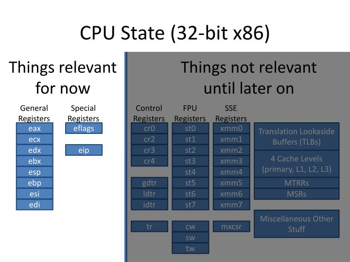
As you master your understanding of x86 architecture, there are a few registers which exist but don't typically get talked about until the very end:
- FLAGS
- Global Descriptor Table (GDT)
- Local Descriptor Table (LDT)
- Interrupt Descriptor Table (IDT)
- Task Register (TR)
- The Instruction Pointer (
IP) register points to the first byte of the next instruction in memory, but cannot be accessed by the programmer directly.
There is a common vernacular across all cpu architectures when describing pointers, which we'll attempt to summarize here.
| Term | Description |
|---|---|
| implied | pre-determined by opcode; no way to affect |
| stack | implied, but affected by stack push/pop |
| register | src/dst operand is a register pro: fast; within cpu. |
| pc-relative | signed (-128,+127) constant disp8 from IP program counter (short jmp/addr) pro: fast; within instruction. ideal for jmp, branching, threading, fwd/bkwd con: limited max range |
| direct | memory address constant via displacement or immediate pro: fast; within instruction con: unchangeable; addr should not be modified once running/cpu-cached |
| indirect | [register or memory] address is pointer to another memory address only variations of JMP and CALL will automatically dereference an indirect address. otherwise, manual dereferencing requires multiple instructions. pro: can change address pointed to at runtime con: slow; requires two or more memory accesses, and the memory to store them |
Effective addresses are any operand to an instruction which references memory.
Calculated in some of the following ways:
-
indexed offset:
segment + base + (scale * index) + displacementA segment address is always implied unless you override the selector.
The rest is optional.
Index defaults to 1 while scale, base, displacement default to 0. -
near pointer "segment_register:offset" or just "offset":
address is relative to given segment register,
otherwise relative to the default segment--which is usually DS but may vary by instruction.
The SEGMENT REGISTERS are: CS, DS, FS, ES, and SS -
far pointer "segment_selector:offset" data type:
two addr concat in single operand
the segment_selector refers to the GDT which refers to a protected memory page
the offset is the address relative to that.
References:
- Using Short/Relative vs. Far Jumps
https://thestarman.pcministry.com/asm/2bytejumps.htm
One of the earliest commercial-grade assembler tools was Microsoft Macro Assembler (MASM) in 1981.
It was initially marketed for commercial use, and included documentation.
Beginning with v7 (1991) it was only available packaged with various
Microsoft SDKs and C compilers, and its license required you to own a copy of
Visual Studio. Since then its documentation has also become sparse and difficult
to get ahold of.
Its early influence led to many derivatives; importantly, it inspired the
open-source Netwide Assembler (NASM) project, which is basically MASM with
improvements that allow it to work across all platforms.
Some hardcore enthusiasts still author primarily in MASM and hoan their techniques by collecting, preserving, and resharing rare code artifacts from fellow enthusiasts.
Today there are numerous assemblers to choose from, including Richard Stallman's
GNU Assembler (GAS) which ships with Linux coreutils, but these are the most
common choices.
References:
- Current [but sparse] Official Microsoft Macro Assembler Reference
https://docs.microsoft.com/en-us/cpp/assembler/masm/microsoft-macro-assembler-reference?view=vs-2017 - PCjs Project: kindly hosted mirror of old Microsoft Macro Assembler 5.00 Manuals (1987)
https://www.pcjs.org/pubs/pc/software/tools/microsoft/masm/5.00/ - Third-party community support forums (anecdotal information and references)
http://www.masm32.com/board/ - Art of Assembly (contains summary of MASM syntax)
http://www.oopweb.com/Assembly/Documents/ArtOfAssembly/Volume/Chapter_8/CH08-1.html#top - Steve Gibson's MASM enthusiast page
https://www.grc.com/smgassembly.htm - Netwide Assembler (NASM) Documentation
https://www.nasm.us/doc/ - NASM Tutorial
http://cs.lmu.edu/~ray/notes/nasmtutorial/ - SASM: Simple crossplatform IDE for NASM, MASM, GAS, FASM assembly languages
https://dman95.github.io/SASM/english.html
References:
- Reversing: Secrets of Reverse Engineering
https://www.amazon.com/Reversing-Secrets-Engineering-Eldad-Eilam/dp/0764574817 - Writing Windows Shell Code
https://www.tophertimzen.com/blog/windowsx64Shellcode/ - x86 Disassemblers and Decompilers
https://en.wikibooks.org/wiki/X86_Disassembly/Disassemblers_and_Decompilers - CheatEngine: A trainer for game hacking, etc.
http://wiki.cheatengine.org/index.php?title=Assembler&redirect=no - Types of Compiler Optimizations (useful to identify what you are reverse engineering)
https://en.wikipedia.org/wiki/Compiler_optimization - GDB Internals
http://wwwcdf.pd.infn.it/localdoc/gdbint.pdf - Windbg Commands
https://docs.microsoft.com/en-us/windows-hardware/drivers/debugger/commands - x86dbg is perhaps the best Windows debugger today
https://x64dbg.com/ - Hex-Rays Interactive Disassembler (IDA); most professional, but expensive
https://www.hex-rays.com/products/ida/index.shtml - Binary Ninja; less featureful but cheap, modern interactive disassembler
https://binary.ninja/ - Reversed non-standard opcode mappings which may confuse normal disassemblers
https://github.com/XlogicX/irasm
Windows executables (*.exe, *.dll) use Portable Executable (PE) format,
which is a wrapper around and Component Object File Format (COFF), which is
used by binary linker files (*.obj, *.lib). Technically Windows 64-bit uses
a version internally called PE32+.
A linker (ie. link.exe, cl.exe, ld, etc.) is basically designed to parse one
or more COFF files, and wrap them into a single executable with a PE header.
Here is some useful trivia about that:
.objis Windows COFF,.ois the equivalent Linux ELF; same purpose, different formats.- Microsoft COFF is an extended version of the original by AT&T.
.objand.libfiles contain a simple table data structure mapping unique ASCII string symbol names to code or address offsets in another file..libmay include source code (static), but most of the time (e.g., in Visual Studio) they are just header stubs (dynamic) with pointers to address offsets in a.dllwhich must match the exact release version and compiler used.- Confusingly, there is no trivial way to tell static and dynamic
.libfiles apart, except that [dynamic] import libraries for DLLs will be much smaller than the matching static library would be. .libfiles may only be used at compile time to build statically linked binaries..dllfiles are intended to only be used at runtime to as dynamically linked binaries.- Technically
.dllfiles contain enough information that a reverse engineer could statically link them without a.lib, if they wanted to. - If you only have a
.dll, you may be missing the compile-time constants passed as function arguments. These are typically shared in the form of a C header (*.h) file, as part of an SDK (e.g, windows sdk , opengl sdk), if the developer wants you to have them. The other thing you may not have is the documentation about what inputs are valid, when, and what effect they have on the.dllfunctions. Though a determined hacker could successfully guess them by looking at example code which uses the.dll, or via fuzz testing. - The version of
gcctoolchain GNU linker (ld) ported to Windows can statically link using.dllinputs directly, which means it is able to implicitly synthesize the normally required but missing.libstubs automagically! - Decorated names or mangled names are a symbol naming convention used in the
COFF files. They are a series of ASCII prefix and suffixes which guarantee that
each function is named uniquely when merged into the same flat COFF table format.
The additional data mangled into the name includes:
- The function name.
- The class name that the function is a member of, if it is a member function.
This may include the class that encloses the class that contains the function, and so on. - The namespace the function belongs to, if it is part of a namespace.
- The C function parameter types, in order.
- The calling convention.
- The return type of the function.
- You can decode decorated/mangled names using supplied tools, like so:
"> C:\Program Files (x86)\Microsoft Visual Studio 14.0\VC\bin\dumpbin.exe" /symbols "C:\Program Files (x86)\Microsoft Visual Studio 14.0\VC\lib\amd64\msvcrt.lib"
"> C:\Program Files (x86)\Microsoft Visual Studio 14.0\VC\bin\undname.exe" "??$?RUTlsDtorNode@@@__crt_internal_free_policy@@QEBAXQEBUTlsDtorNode@@@Z"
Undecoration of :- "??$?RUTlsDtorNode@@@__crt_internal_free_policy@@QEBAXQEBUTlsDtorNode@@@Z"
is :- "public: void __cdecl __crt_internal_free_policy::operator()<struct TlsDtorNode>(struct TlsDtorNode const * __ptr64 const)const __ptr64"
References:
- PE Format
https://docs.microsoft.com/en-us/windows/desktop/Debug/pe-format - MSDN Article from 2002 going into tremendous depth on history and intentions
http://www.delphibasics.info/home/delphibasicsarticles/anin-depthlookintothewin32portableexecutablefileformat-part1
http://www.delphibasics.info/home/delphibasicsarticles/anin-depthlookintothewin32portableexecutablefileformat-part2 - MSDN Article from Mar 2002 detailing steps the Windows Loader takes with PE binaries
https://www.cnblogs.com/binsys/articles/2711010.html - Peering Inside the PE: A Tour of the Win32 Portable Executable File Format
https://msdn.microsoft.com/en-us/library/ms809762.aspx - Portable Executable
https://en.wikipedia.org/wiki/Portable_Executable - Official Microsoft PE/COFF Technical Specification for Rev 6., 1999
https://courses.cs.washington.edu/courses/cse378/03wi/lectures/LinkerFiles/coff.pdf - Handy Quick-Reference Posters
https://github.com/corkami/pics/blob/master/binary/README.md#executables - CFF Explorer Suite: view structure of PE files (not COFF files tho)
https://ntcore.com/?page_id=388 - PEView: view structure of 32-bit PE/COFF files
http://wjradburn.com/software/ - Difference between .lib and .dll
http://www.differencebetween.net/technology/difference-between-lib-and-dll/ - Decorated/Mangled Names
https://docs.microsoft.com/en-us/cpp/build/reference/decorated-names?view=vs-2017 - Linking Explicitly
https://msdn.microsoft.com/en-us/library/784bt7z7.aspx - Creating the smallest possible PE executable
https://web.archive.org/web/20101024125357/http://www.phreedom.org:80/solar/code/tinype/ - DLL search order
https://docs.microsoft.com/en-us/windows/desktop/dlls/dynamic-link-library-search-order - CppCon 2017: James McNellis “Everything You Ever Wanted to Know about DLLs”
https://www.youtube.com/watch?v=JPQWQfDhICA - Address Space Layout Randomization (ASLR)
https://en.wikipedia.org/wiki/Address_space_layout_randomization - In 2017 "ASLR⊕Cache" attack demonstrated defeating ASLR from a web browser using JavaScript
https://www.vusec.net/projects/anc/ - NTSTATUS values (Windows %errorlevel% codes)
https://msdn.microsoft.com/en-us/library/cc704588.aspx - Official intro and reference for Windows-based graphical user interfaces
https://docs.microsoft.com/en-us/windows/desktop/winmsg/windowing - Windows System Error Codes
https://docs.microsoft.com/en-us/windows/desktop/Debug/system-error-codes
References:
- Executable and Linkable Format
https://en.wikipedia.org/wiki/Executable_and_Linkable_Format - ELF-64 Object Format
http://ftp.openwatcom.org/devel/docs/elf-64-gen.pdf - Creating Really Teensy ELF Executables
http://www.muppetlabs.com/~breadbox/software/tiny/teensy.html - C fork() function
https://www.thegeekstuff.com/2012/05/c-fork-function/ - Handy Quick-Reference Posters
https://github.com/corkami/pics/blob/master/binary/README.md#executables
References:
- Abstract Syntax Tree
https://en.wikipedia.org/wiki/Abstract_syntax_tree
http://www.peroxide.dk/download/tutorials/pxdscript/chapter3.html - Let's Build a Compiler, Jack W. Crenshaw, 2012
https://www.stack.nl/~marcov/compiler.pdf - Optimizing Compiler Passes
https://blogs.msdn.microsoft.com/ericlippert/2010/02/04/how-many-passes/ - Coroutine
https://en.wikipedia.org/wiki/Coroutine - Writing an Interpreter + Compiler in Golang
https://interpreterbook.com/
- The x86 Instruction Structure
https://www.codeproject.com/articles/662301/x-instruction-encoding-revealed-bit-twiddling-fo - X86-64 Instruction Encoding
https://wiki.osdev.org/X86-64_Instruction_Encoding - CPU Rings Privilege and Protection
https://manybutfinite.com/post/cpu-rings-privilege-and-protection/ - Interesting overview from Haskell to Machine code
http://www.stephendiehl.com/posts/monads_machine_code.html - Intel: Introduction to x64 Assembly (an official guide)
https://software.intel.com/en-us/articles/introduction-to-x64-assembly/ - Punching Cards (for FORTRAN programming)
https://www.youtube.com/watch?v=oaVwzYN6BP4 - Visual x86, x64, and ARM Emulator
https://www.codeproject.com/Articles/478527/X86-ARM-Emulator - Build an 8-bit computer from scratch
https://eater.net/8bit/parts - C to Linux x86-64 Assembly (ASM) examples
https://gist.github.com/mikesmullin/6330894 - Linux x86_64 Syscall Table
http://blog.rchapman.org/posts/Linux_System_Call_Table_for_x86_64/ - How Rust encodes exceptions and interrupts
https://os.phil-opp.com/handling-exceptions/ - NeHe's famous OpenGL game dev tutorials incl. examples in Windows MASM
http://nehe.gamedev.net/tutorial/creating_an_opengl_window_(win32)/13001/ - How Debuggers Work w/ Breakpoints
https://eli.thegreenplace.net/2011/01/27/how-debuggers-work-part-2-breakpoints - Ralf Brown's BIOS Interrupt List
http://www.ctyme.com/rbrown.htm - Agner Fog's books and blog, reknown for advanced assembly information
https://www.agner.org/optimize/ - Intel® 64 and IA-32 Architectures Software Developer Manuals
https://software.intel.com/en-us/articles/intel-sdm - AMD64 Architecture Programmer's Manual
https://www.amd.com/system/files/TechDocs/24594.pdf