Original blog post by Kako: http://www.kako.com/neta/2007-001/2007-001.html
Hand-translated to English by multiplemonomials
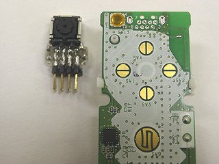
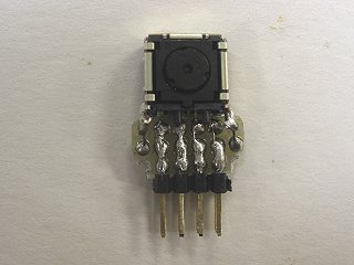
I took the infrared sensor from the PCB inside the remote, and I tried attaching an 8 pin (4 pins in two rows) connector to it.
First of all, I took a look into the functions of these 8 pins. The results are as follows:
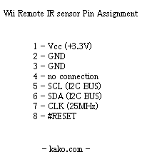
(Updated 1/31/2007: Pin 4 seems to be the #CE signal.)
Next, following the path above, to confirm whether the infrared sensor works I built and tested some homemade circuitry.
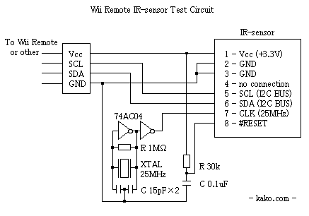
(Updated 1/31/2007: Because Pin 4 is the #CE signal, you should connect it to GND.)
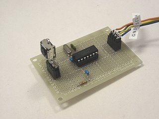
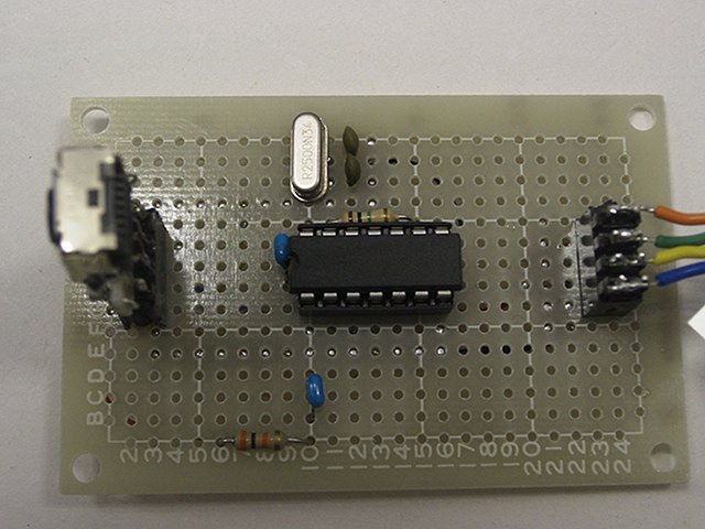
I connected the VCC, SCL, SDA, and GND signals to the PCB of the Wii remote that I dismounted the sensor from. With the wires attached, I then tried some movements with the remote, and confirmed that the cursor moved just as always.
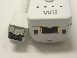
By the way, I also knew that the I2C signals from the Wii remote are available on its expansion port. The Nunchuck and the Classic Controller also connect through the I2C bus. Because I2C is hot-swappable, you can also use it for this purpose.
Expansion Port Pin for Nunchaku/Classic Controller
- Vcc
- SCL
- Connect to 1 (for connection detection)
- n.c.
- SDA
- GND
(Pin 4 is unconnected on the Nunchuck and Classic Controller, but is connected to some kind of circuit on the Wii Remote. Maybe for a vibration pack [AKA Rumble Pak -TR]? Something installed between the Classic Controller and the Wii Remote?)
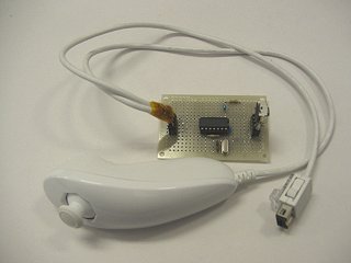
I cut the Nunchuck controller cable right in the middle, and plugged the IR sensor into the expansion port:
(Wii Remote w/out IR sensor) → (IR sensor circuit board & relay connector) → (Nunchuck controller)
This way, I could use the IR sensor I took from the Wii remote without it being physically inside the remote.
With the 3rd pin of the expansion port detected, if I disconnected the cable from the nunchuck connector, the Wii remote would freeze. To prevent it from freezing, you should hook it up as above. (Updated 1/30/2007: I said that connecting pins 1 and 3 of the expansion port would cause it to freeze, but I couldn't reproduce this when I tried again. Probably a mistake in my work shorted other signals and caused the freeze).
Besides the IR sensor, it's possible that any I2C device could be connected to the Wii remote expansion port. If so, homemade peripherals for the Wii remote should be possible.
To sum up, there are two practical uses of the expansion port:
- Connecting any kind of device that uses I2C signaling in order to operate custom peripherals with the remote.
- Connecting the remote to a PC and putting it in a command state, then connecting the I2C lines to another master. Then, from outside the remote, one can access I2C devices inside the remote (such as the EEPROM).
Inside the remote, there's an EEPROM connected to the I2C bus. It stores things like Mii data and the Bluetooth ID. This is unconfirmed information, but it seems like something like binary data in the EEPROM is loaded and executed by the CPU. If this is true, by modifying this data, it may be possible to upload code into the Wii remote and hack it. Using the expansion port method (as above), you can read the data from this EEPROM, but writing to it gave me difficulties. I even tried using Bluetooth, but it seems that the addresses behind the EEPROM [not sure what that means -TR] have been locked so they can't be read or written. Changing the data without taking apart the remote and removing the EEPROM IC seems impossible.
Next, without using the Wii Remote, I tried connecting the IR sensor to another device that can act as an I2C master. To give the conclusion first, by sending and receiving commands just as the Wii Remote does, a light source like the Sensor Bar can be detected (1/25/2007).
To use the I2C bus from a PC, I used a peripheral called the USB-I2CIO from DeVaSys [see here -TR]. You connect it to a PC via USB, and it functions as an I2C master. It also includes general purpose I/O functions.
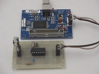
The four wires for VCC (3.3V), GND, SCL, and SDA were connected as before.
Here's when I tried some real movements with it: (download, 2.0MB MPEG-1 format video).
I downloaded the library for controlling the USB-I2CIO from DeVaSys's website, and using it I wrote a C program myself to send and receive commands from the infrared sensor.
(If I make the software public, I don't think there's anyone who will use it. If someone says they made the same board and is hoping for it, I'll probably send it to them individually. For the time being, I'm still reorganizing it.)
(2/2/2007 I made the Wii-Tenkey (wii number pad)) (2/7/2007 I made the Wii-Gyro)
(Updated 2/22/2008: I tried out the REX-USB61 I2C interface [see here -TR], which is available domestically in Japan. First I rewrote the part of the code that calls the library, then used the rest of the software unchanged. As always, I haven't finished adjustments to the code. I haven't completely abandoned the project, and it's still ongoing.)
(Updated) Circuitry and code has been publically released for connecting the sensor to an Atmel AVR.
(Updated 12/24/2013) The infrared sensor inside the Wii remote appears to have been switched with a different model. I took one apart and investigated.