Out of the box, the MakerFabs ESP8266 shield appears to be shipping with a broken firmware that is unstable when used with DCC-EX. I needed to flash version 1.7.4 onto the board. Here's how I did it - hopefully it works for you.
- The WiFi Shield itself - https://www.makerfabs.com/esp8266-wifi-shield.html
- USB to TTL adapter - https://www.amazon.com/gp/product/B07D6LLX19/
- 4x female to female jumper wires
- 1x male to male jumper wire
- The flash download tool and firmware files from DCC-EX - https://dcc-ex.com/download/esp8266.html
- A Windows PC
- Extract both the download tool and firmware files zips
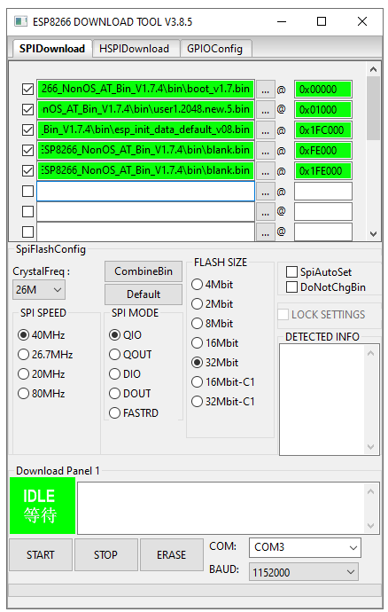
- Open the download tool, select "Developer Mode", then "ESP8266 DownloadTool".
- Ensure all these settings in the screenshow are set. Take special note of the files and the offset number next to them.
- Ensure all five files are green - enable the checkbox next to each file after setting it.
- Ensure the COM port is set to that of your adapter (You can find this in device manager after plugging it in and installing drivers).
- Leave the window open, but DO NOT PRESS START YET.
Assuming you're using a similar adapter to the one I linked to above:
- Connect one jumper wire from the "+5V" pin on the adapter to the underside of the "5V" pin on the WiFi shield
- Connect one jumper wire from the "GND" pin on the adapter to the underside of the "GND" pin on the WiFi shield
- Connect one jumper wire from the "RXD" pin on the adapter to one of the "ESP_TX" pins on the top of the WiFi shield
- Connect one jumper wire from the "TXD" pin on the adapter to one of the "ESP_RX" pins on the top of the WiFi shield
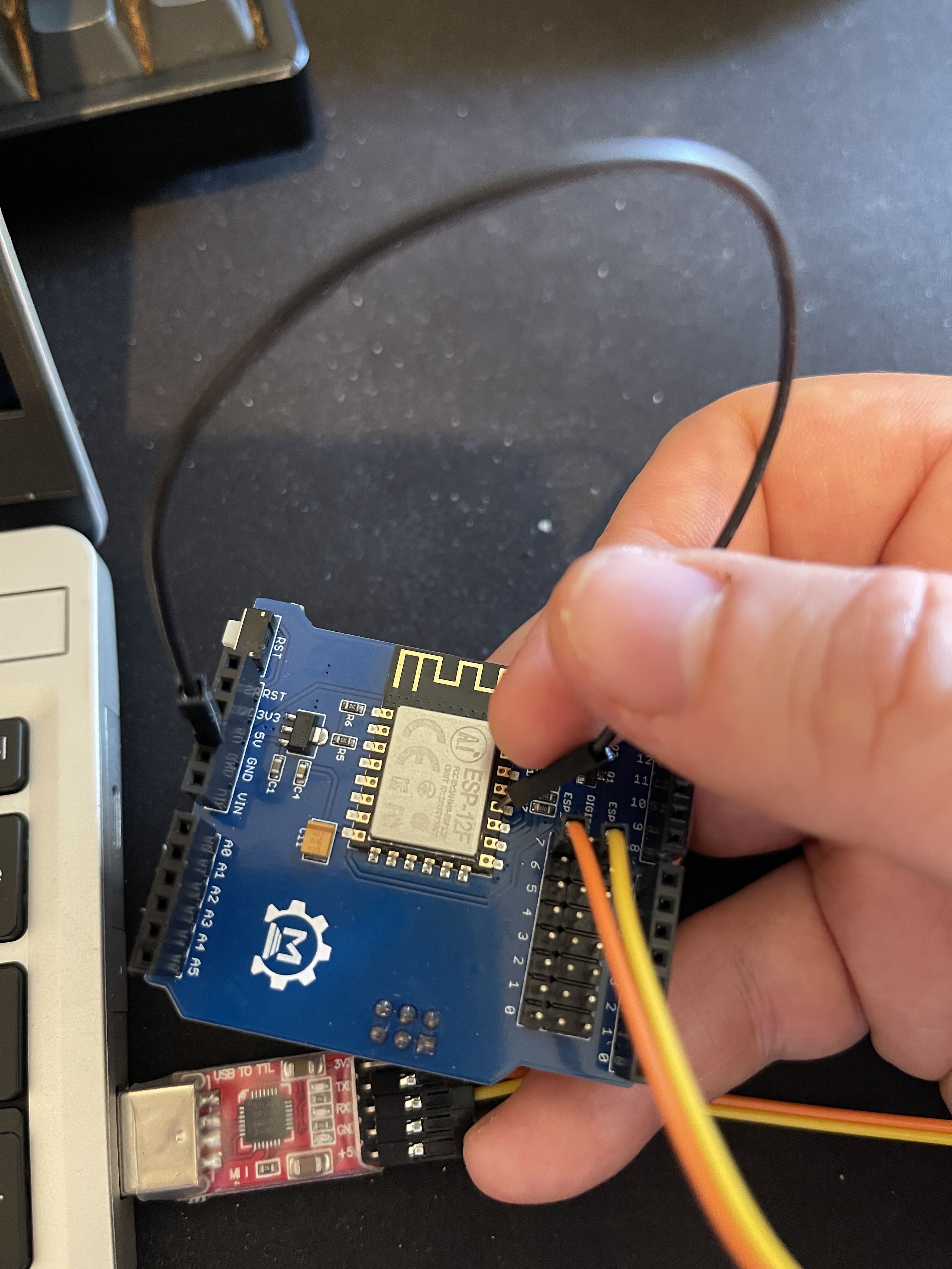
Your connections should look like this:

The adapter should be unplugged from the USB port at this stage.
- Connect one end of the the male-to-male jumper to the top of the "GND" pin on the WiFi shield.
- Hold the other end of the male-to-male jumper onto the GPIO0 pin on the ESP-12F. (Note: The GPIO0 pin is the fourth pin from the bottom on the right, next to the "P" in "ESP-12F". See picture below.
- KEEP HOLDING THE JUMPER ON THE PIN
- Plug the adapter into a free USB port on your PC
- KEEP HOLDING THE JUMPER ON THE PIN
- KEEP HOLDING THE JUMPER ON THE PIN
- Return to the download tool.
- Press start.
- KEEP HOLDING THE JUMPER ON THE PIN
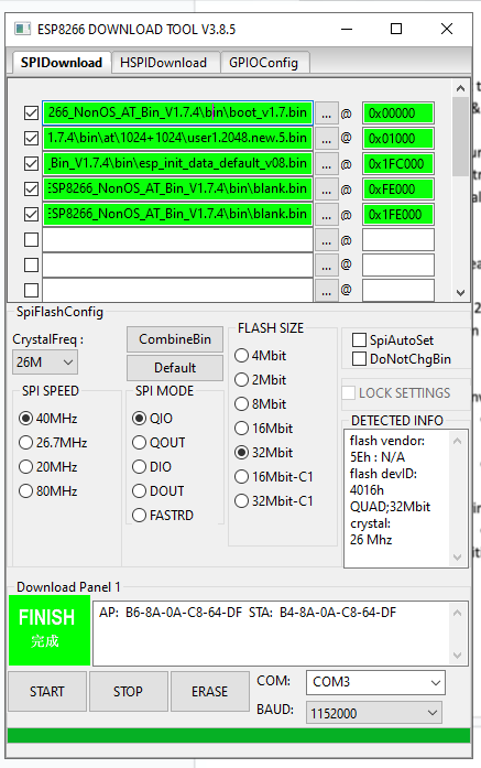
- Wait until the green box in the tool says "FINISH".
- You can let go of the jumper now. :)
If you get an error, unplug the adapter, plug it back in, and press Start again. It can take a couple of tries. BUT KEEP HOLDING THE JUMPER ON THE PIN.
If at any point you let go of the jumper, unplug the adapter from the USB port, place the jumper back on the pin, and plug it back in, then click Start again. Remember to keep holding it.
When finished, it should look like this.
You should now be able to unplug the WiFi shield, place it onto your DCC-EX setup, and if all went well it should work.


Had no luck with version 3.8.5 of the tool at all and kept failing with an EFUSE. Downloaded version 2.3. (link in DCC EX article). Deleted the config file that came with it (this caught me out) and to be on the safe side copied the files into the same directory I ran the tool from.
Prefect.. ran straight trough no problems, had a second board so repeated the process and again success. Happy as I had spent several hours with version 3 of the tool going no where.
Installed back on Arduino stack and checked.. Back leveled to 1.7.4.
Final part or the console output below.
Hope this helps
Panel1\blank.bin
offset : 2088960
Erasing flash...
head: 1 ;total: 1
erase size : 4096
Writing at 0x00000c00... (0 %)
Leaving...
Erasing flash...
head: 15 ;total: 101
erase size : 352256
Writing at 0x00065c00... (97 %)
Leaving...
Erasing flash...
head: 1 ;total: 1
erase size : 4096
Writing at 0x000fec00... (98 %)
Leaving...
Erasing flash...
head: 1 ;total: 1
erase size : 4096
Writing at 0x001fc000... (98 %)
Leaving...
Erasing flash...
head: 1 ;total: 1
erase size : 4096
Writing at 0x001fec00... (99 %)
Leaving...
com closed