Skip to content

Instantly share code, notes, and snippets.

@nathankellenicki
Last active December 8, 2023 03:23
Show Gist options
  • Star 1 You must be signed in to star a gist
  • Fork 0 You must be signed in to fork a gist
  • Save nathankellenicki/7008540322c617869cec17226cff579d to your computer and use it in GitHub Desktop.
Save nathankellenicki/7008540322c617869cec17226cff579d to your computer and use it in GitHub Desktop.

Intro

Out of the box, the MakerFabs ESP8266 shield appears to be shipping with a broken firmware that is unstable when used with DCC-EX. I needed to flash version 1.7.4 onto the board. Here's how I did it - hopefully it works for you.

Requirements

How To

Step 1 - Set up the download tool

  1. Extract both the download tool and firmware files zips
  2. Open the download tool, select "Developer Mode", then "ESP8266 DownloadTool".
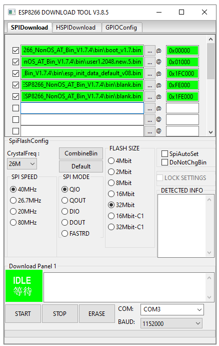
  3. Ensure all these settings in the screenshow are set. Take special note of the files and the offset number next to them.
  4. Ensure all five files are green - enable the checkbox next to each file after setting it.
  5. Ensure the COM port is set to that of your adapter (You can find this in device manager after plugging it in and installing drivers).
  6. Leave the window open, but DO NOT PRESS START YET.

Screenshot (136)

Step 2 - Connect the Jumper Wires

Assuming you're using a similar adapter to the one I linked to above:

  1. Connect one jumper wire from the "+5V" pin on the adapter to the underside of the "5V" pin on the WiFi shield
  2. Connect one jumper wire from the "GND" pin on the adapter to the underside of the "GND" pin on the WiFi shield
  3. Connect one jumper wire from the "RXD" pin on the adapter to one of the "ESP_TX" pins on the top of the WiFi shield
  4. Connect one jumper wire from the "TXD" pin on the adapter to one of the "ESP_RX" pins on the top of the WiFi shield

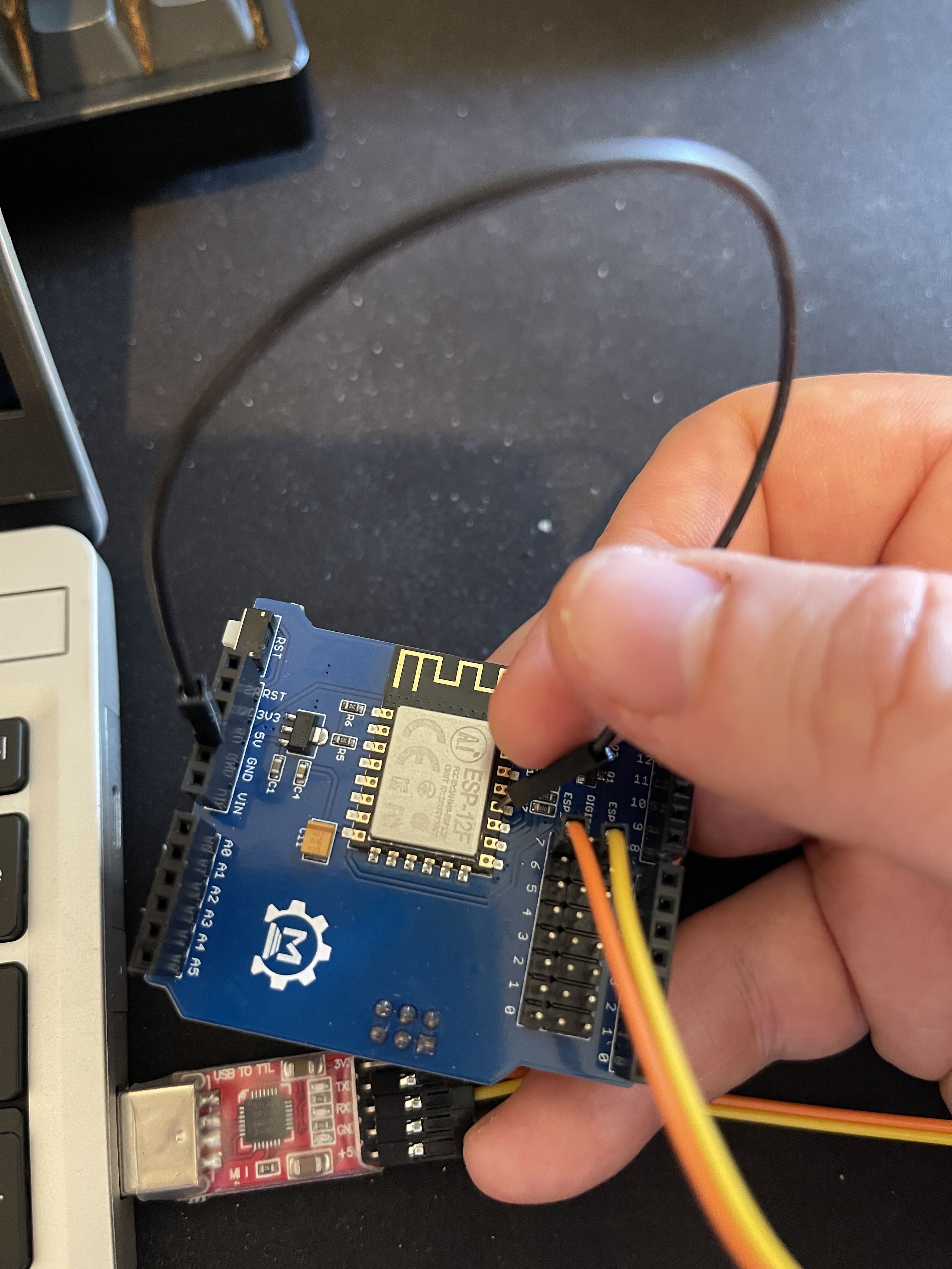
Your connections should look like this:

IMG_0372

Step 3 - Plug in the adapter.

The adapter should be unplugged from the USB port at this stage.

  1. Connect one end of the the male-to-male jumper to the top of the "GND" pin on the WiFi shield.
  2. Hold the other end of the male-to-male jumper onto the GPIO0 pin on the ESP-12F. (Note: The GPIO0 pin is the fourth pin from the bottom on the right, next to the "P" in "ESP-12F". See picture below.
  3. KEEP HOLDING THE JUMPER ON THE PIN
  4. Plug the adapter into a free USB port on your PC
  5. KEEP HOLDING THE JUMPER ON THE PIN

IMG_0376

Step 4 - Start the flashing

  1. KEEP HOLDING THE JUMPER ON THE PIN
  2. Return to the download tool.
  3. Press start.
  4. KEEP HOLDING THE JUMPER ON THE PIN
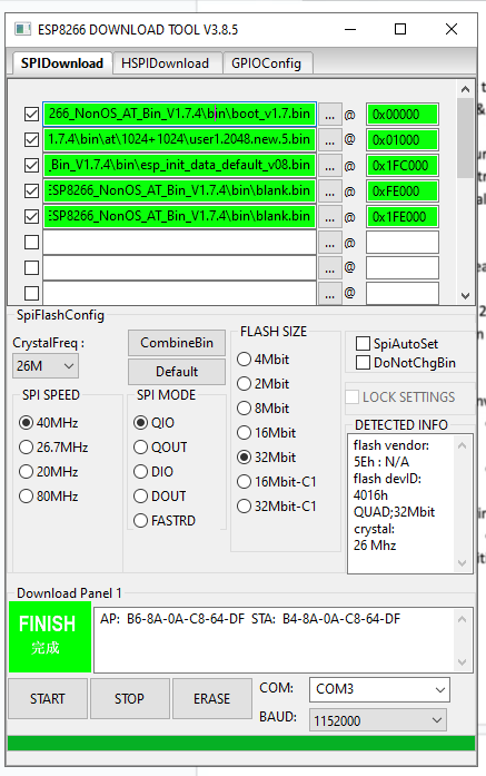
  5. Wait until the green box in the tool says "FINISH".
  6. You can let go of the jumper now. :)

If you get an error, unplug the adapter, plug it back in, and press Start again. It can take a couple of tries. BUT KEEP HOLDING THE JUMPER ON THE PIN.

If at any point you let go of the jumper, unplug the adapter from the USB port, place the jumper back on the pin, and plug it back in, then click Start again. Remember to keep holding it.

When finished, it should look like this.

Screenshot (134)

Step 5 - Use the WiFi shield

You should now be able to unplug the WiFi shield, place it onto your DCC-EX setup, and if all went well it should work.

@foxe117
Copy link

foxe117 commented Oct 13, 2023

How did you add files to the developer tool?

@dem368
Copy link

dem368 commented Nov 8, 2023

I've gotten to Step 1, #3. Are the settings typed in or automatically input? I tried typing them in but they turned red. I see that the bins are in file folders. Do the folders need to be opened? How does one get the settings into the download tool. HELP!

@dem368
Copy link

dem368 commented Nov 9, 2023

After much trial and error I successfully reached "Finish". Here's what I learned. The settings for the download tool are neither typed in nor automatically loaded. They are binary files inside the "ESP8266_NonOs_AT_Bin_V1..4" file and they need to be attached to the download tool. There are many items in this file after all the file folders are opened, but the four needed are all ".bin" files: boot_v1.7.bin, user1.1024.new.5.bin' esp_init_data_default_v08.bin and blank.bin. Loading these files to the download tool is similar to attaching a file to an email. Click the ... Button. A window opens permitting you to browse your files and find the right bin file. When found click it, and when it appears below click the Open Button. The file will be loaded to the tool and will turn green. NOTE that only the last part of the line will look like the example above. The parts to the left are the path to the file on your computer and will never look like the example. Continue to load all five lines. The boxes to the right must be typed in accurately. Note that the first character is zero and NOT a capital o.

Now for the bloody IZOKEE adapter. It needs a driver. Most of the time when a new device is plugged in, Windows searches its inventory of drivers and installs the right one automatically. In my case, Win10 crossed its arms and said "It don't recognize this device and can't help you." Off to the internet to find a driver. There are many warnings that loading a driver manually is difficult. Loading a driver manually is easy; finding the right driver is difficult. I settled on the Silicon Labs universal CP210x driver for windows. I suggested inserting the adapter into a USB port and getting it setup before attaching the jumper wires. Use Device Manager to do this. Win10 set it up as COM4. So at the bottom of the tool in the box to the the right of COM: I inserted COM4. I got "Open Port Failure" over and over. Finally I deleted "COM4" and entered just 4. Three seconds later it was done. I WISH I HAD KNOWN ALL THIS BEFORE I STARTED THE JOURNEY.

@Ri-Pete
Copy link

Ri-Pete commented Nov 15, 2023

I have everything connected and all is green. I hit start and the adapter flashes 5 times fast twice then there is a slight pause and again 5 times fast twice. This has been doing this for over 8 hours and no finish has come on yet. The 8266 led is weakly flashing and seems to be getting some kind of signal but 8 hours???? Is there a video of anyone doing this that I can watch that is completely understandable?

@dem368
Copy link

dem368 commented Nov 16, 2023 via email

@Ri-Pete
Copy link

Ri-Pete commented Nov 16, 2023

I’ve rerun it over a dozen times and all I get is the 5 + 5 flashes, no “Finished”. It still says idle.
When I hit “stop”, it says “failed to sync”.
I soldered the ground wire to the 4th pin on the ESP-12F (holding it for 3 seconds I could have done, not for hours).
When I look at the command prompt window, all it shows is *****_____*****_____*****_____*****_____
*****_____*****_____*****_____*****_____*****_____*****_____
*****_____*****_____*****_____*****_____*****_____*****_____.
I’ve put in all the correct 0x #’s correctly, checked and confirmed the controller had the most recent driver and it was on com 4, set it up at Baud 115200, so I’m not sure what I did wrong.
I’ll check later today to see what it says now.
Pete

@ManicMayhem
Copy link

ManicMayhem commented Nov 22, 2023

Had no luck with version 3.8.5 of the tool at all and kept failing with an EFUSE. Downloaded version 2.3. (link in DCC EX article). Deleted the config file that came with it (this caught me out) and to be on the safe side copied the files into the same directory I ran the tool from.

Prefect.. ran straight trough no problems, had a second board so repeated the process and again success. Happy as I had spent several hours with version 3 of the tool going no where.

Installed back on Arduino stack and checked.. Back leveled to 1.7.4.

Final part or the console output below.

Hope this helps

Panel1\blank.bin
offset : 2088960
Erasing flash...
head: 1 ;total: 1
erase size : 4096
Writing at 0x00000c00... (0 %)
Leaving...
Erasing flash...
head: 15 ;total: 101
erase size : 352256
Writing at 0x00065c00... (97 %)
Leaving...
Erasing flash...
head: 1 ;total: 1
erase size : 4096
Writing at 0x000fec00... (98 %)
Leaving...
Erasing flash...
head: 1 ;total: 1
erase size : 4096
Writing at 0x001fc000... (98 %)
Leaving...
Erasing flash...
head: 1 ;total: 1
erase size : 4096
Writing at 0x001fec00... (99 %)
Leaving...
com closed

@1956Porsche
Copy link

I have downloaded the download tool and firmware. I can also see the four .bin files that dem368 describes in his comments, but I'm lost in the details and explanation on attaching the files to the download tool.

@ManicMayhem
Copy link

Right click on the 3 dots (•••) to the left of @.
then chose the file. You need to do each on individually.
add the correct addressing nest to each file and then tick each box on the right. They should go greening the paths correct.

@1956Porsche
Copy link

I was able to attach all of the bin files and correct addressing nests. I did a couple of starts but finally got a "Finish". I reinstalled the installer and device monitor shows AT Version:1.7.4.0 May 11 2020 19:13. Setup Wi-Fi as stand along network. Before updating firmware, network ID was showing DCEX_433bd3 and connected fine on my Android phone, but now shows DCCEX_f343b4 and shows a connected without internet message. Any suggestions?

@ManicMayhem
Copy link

If your running in AP mode then there will be no internet connection as you connect your phone directly to the WiFi of the stack. I must be honest I didn’t notice if the MAC address of the WiFi changed after flashing but if it has the default password to connect will also have changed as it is made up of the last 6 characters of the MAC address. Check the he SCC EX documentation I think it tells you there. Also prior to back levelling the firmware I could not get it to connect to my own WiFi network. The IP address would not change. It will now and it all works fine. Check example.config.h or config.h if you have one as these affect how the WiFi connects. Sorry if I’m teaching you how to suck eggs.

@colby2h
Copy link

colby2h commented Dec 8, 2023

I had trouble getting this to work. Tried both versions of the installer and seemed to have more luck with version 2.3. I wasn't able to get anything to work with the adapter until I found a driver and installed it for the adapter, afterwards the adapter would light up while running the installer, but still popped up with an error. Pictures on the setup are attached below.
Error
jumpers1
jumpers2
adapter

Sign up for free to join this conversation on GitHub. Already have an account? Sign in to comment