Skip to content

Instantly share code, notes, and snippets.

@darconeous
Last active December 7, 2024 17:45
Show Gist options
  • Save darconeous/8c7899c4d2f849b881d6c43be55066ee to your computer and use it in GitHub Desktop.
Save darconeous/8c7899c4d2f849b881d6c43be55066ee to your computer and use it in GitHub Desktop.
Hacking the Rectangular Starlink Dishy Cable
@jbowler
Copy link

jbowler commented Feb 7, 2023

@morehardware: Would it not be because the Dishy always engages the motors when you plug in as it boots up.

This is my best guess too. My second best guess is that it fires up the antenna array trying to find all the satellites. If it is the motors that is an inductive load and it is pretty much certain that the NF-488 is outputting VA, not W. This doesn't matter from the point of view of frying the ethernet transformers; that depends on the amperage, but the currents I've seen are well within the range the Tycon supports. Since the peak seems to happen around 30s after boot it may be the cause of your problem.

I can't find any wisdom online about using a switching PSU with an inductive load. There is lots of stuff about switching the load itself of course, but I'm sure the antenna is set up to deal correctly with that. I also don't know from my experiments what the true maximum load, minimum voltage and maximum amperage are. Today's exciting job is to wire one of these into the power supply:

https://www.amazon.com/dp/B0BGPG9NVR

This has minimum/maximum readouts with sub-second sampling; apparently below 0.4s. It's main display is an "instantaneous" reading, actually the average over the last 0.4s but it retains averages since start-up as well.

@WIMMPYIII
Copy link

@morehardware: Would it not be because the Dishy always engages the motors when you plug in as it boots up.

This is my best guess too. My second best guess is that it fires up the antenna array trying to find all the satellites. If it is the motors that is an inductive load and it is pretty much certain that the NF-488 is outputting VA, not W. This doesn't matter from the point of view of frying the ethernet transformers; that depends on the amperage, but the currents I've seen are well within the range the Tycon supports. Since the peak seems to happen around 30s after boot it may be the cause of your problem.

I can't find any wisdom online about using a switching PSU with an inductive load. There is lots of stuff about switching the load itself of course, but I'm sure the antenna is set up to deal correctly with that. I also don't know from my experiments what the true maximum load, minimum voltage and maximum amperage are. Today's exciting job is to wire one of these into the power supply:

https://www.amazon.com/dp/B0BGPG9NVR

This has minimum/maximum readouts with sub-second sampling; apparently below 0.4s. It's main display is an "instantaneous" reading, actually the average over the last 0.4s but it retains averages since start-up as well.

It would be awesome to have these numbers documented. Warm boot up, sub 0 boot up, boot up simulating ice or physical block resisting the motor. Heater pre heat, heater auto. Heater off then back on after deep freeze.

@WIMMPYIII
Copy link

I would be nice to have something that could to an actual log.
Saw this, i don't know of there are any cheaper options available.
https://powerwerx.com/west-mountain-radio-pwrcheck-plus-usb

@jbowler
Copy link

jbowler commented Feb 7, 2023

@WIMMPYIII; there is this too:

https://www.amazon.com/gp/product/B00I2XI8P6

But, yeah, the dataloggers seem to be expensive. My Fluke 189 can log one channel (pretty much just logging A is sufficient) but I don't have the dongle/FlukeView sw. IRC my oscilloscope has some support for a serial connection and it has two channels. For the moment I'm logging by eye. This is what I have so far, just using the NF-488. First column is with it in in-line PoE mode, second is measuring the DC port to the Tycon. It has no min/max and the numbers change pretty fast. I'm tempted just to take a time lapse series of photographs, or a movie :-)

StarLink antenna power consumption    
Tester NF-488 NF-488 DC
Boot 0~15s 15W 2-7W
Boot 15s+ 20-82W 15-90W
Boot around 30s for several s 82W 80W
After boot 20-60W 15-80W
External temperature (celsius) -1C -1C
With pre-heat 55-81W  
Snowmelt no change  

@morehardware
Copy link

morehardware commented Feb 7, 2023 via email

@jbowler
Copy link

jbowler commented Feb 7, 2023

I think disconnecting the motors might be a lower draw … can you test again with motors unplugged ?

0.35A, 16.8W flat after stowing. No detectable power/current increase using the NF-488 while stowing or while unstowing. The NF-488 readings jump around continuously while the dish is unstowed. I'm not going to take the antenna apart; if something goes wrong with it I want to be able to ask StarLink for a replacement. Curiously I got the replacement router today and they didn't ask for an RMA of the old one, presumably it is as cheap and unrepairable as it looks. So I need to test that as well then I'll put the new tester inline after that, along with data logging the startup costs with a camera. With any luck the output will be more stable, if not it may be necessary to use an oscilloscope to make sense of the power draw.

@jbowler
Copy link

jbowler commented Feb 9, 2023

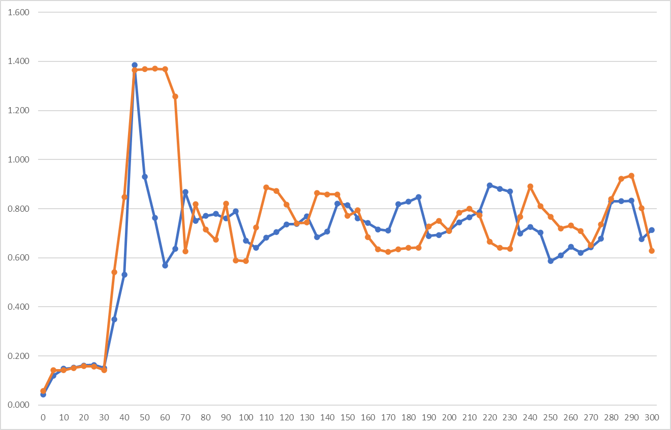
Here's the current consumption in A for the first five minutes. The horizonal axis is seconds; blue is the average every 5s and orange should be the maximum in the same period (Fluke 189 normal min-max). Note that the two lines come from different boots:

image

I've got average values out to 1200s; twenty minutes, but it's just more of the same.

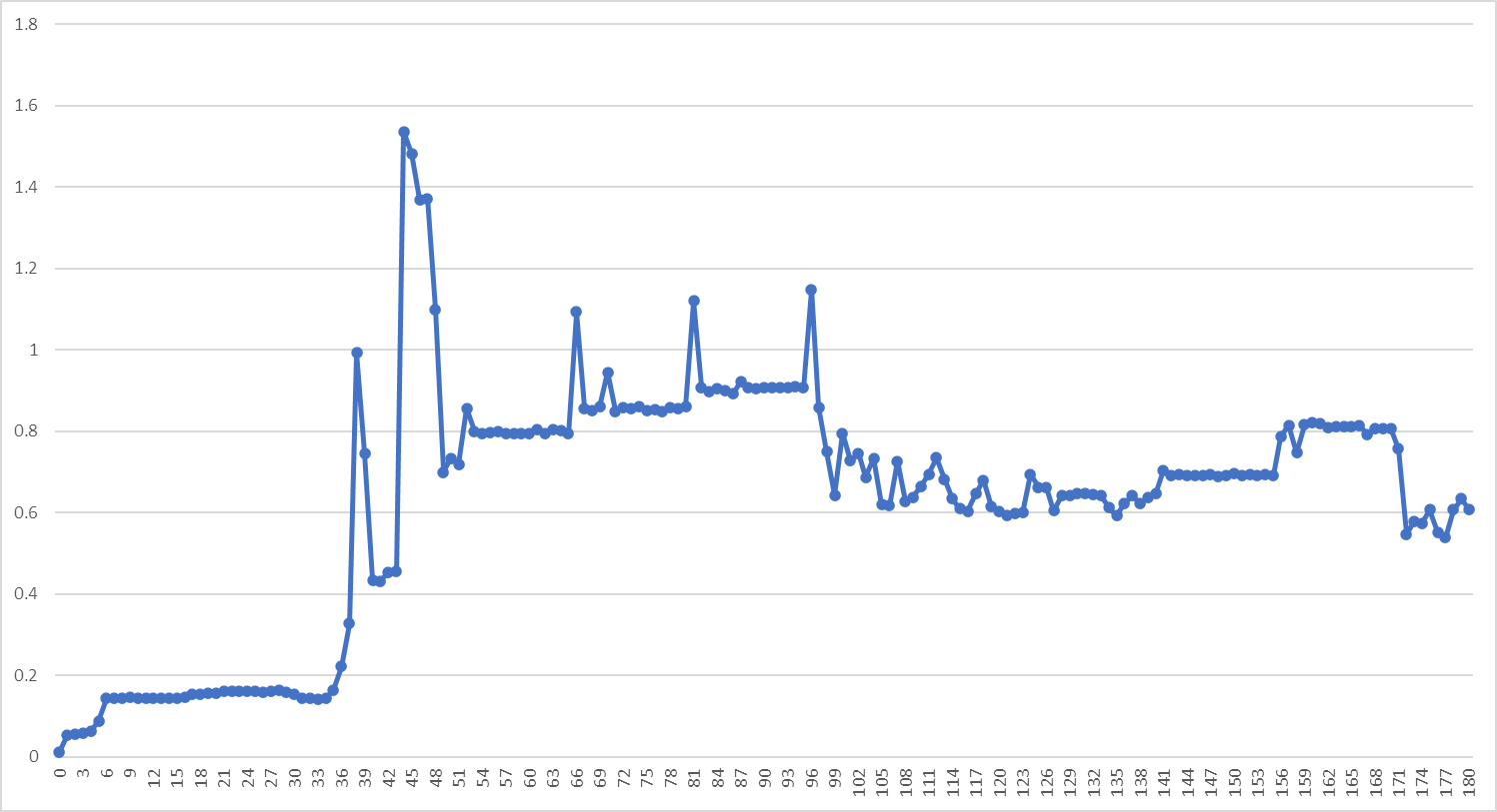
Here's another boot but showing the average current over each 1s period for the first three minutes:

image

The voltage delivered by the PSU is in the same range as above; within 0.5V of 48V. The PSU is a 3A PSU so isn't near the limit. I got these numbers using the data logging of a Fluke 189, typing them into Excel by hand. The "high precision watt meter and power analyzer turned out to be not very useful. It records a peak current of 14A as soon as it starts up... This was worrying so I used the fast min-max on the Fluke 189 to check the inrush; it was actually 6A!

The problem was that I was powering up/down by pulling the barrel connector on the DC (48V) side. DO NOT DO THIS! It causes a massive inrush. The Fluke fast min-max samples across a time of something like 250us, but all the same that kind of current could cause sparking and maybe damage something. The antenna magnetics are apparently some kind of custom Würth Elektronik 4PPoE++ device; they don't list the part number but other magnetics in the series can go up to 1500mA/pair (per centre tap); so that's a 3A/150W supply. All the same 6A is too much.

I changed my methodology to powering up/down on the AC side; pull the plug on the PSU. This results in a soft start; fast min-max does not register a surge. The initial startup current is around 55mA for the first 5s, it then jumps to around 150mA for the next 30s then goes to the highs seen immediately afterward; 1A at 38s 1.5A at 45s. The long term average is 700mA but as can be seen from the first graph it swaps between around 600mA and 900mA for intervals of maybe 30s.

To get wattages at the PSE multiply by 48. At the PD, the antenna, there will be a 75ft/18AWG drop forward and back; four 24AWG 7/32 conductors in parallel have the same cross-section as 1 18AWG 7/26. The total resistance is about 0.9ohm, so assume 1.5V drop at the PD at 1.5A; multiply by 46.5

This is without pre-heat but the pre-heat didn't seem to add more than 0.25A. Everything seems to be well within the rating of the router PoE; 2A at 48V. I don't know where all this stuff about massive power requirements comes from, maybe the V1 and V2 dishes? Certainly the rectangular dish (V3) does not need more than 96W at the PSE, i.e. more than 2A, whatever the custom magnetics in the dish do.

I also ran the system from boot with fast min-max on the Fluke 189. This gave me an average over an hour of 0.7A and a transient peak of 3.4A. Bear in mind that this is a transient; it's coming out of the PSE capacitor which, as my do not do this above demonstrates is perfectly capable of delivering 6A in a single transient. There does always seem to be a transient in the first minute; presumably the 45s peak above. It varies between boots, one gave me 2.98A the other 3.34A. There was a second transient after about 17m of 3.39A so my assumption is that these transients happen irregularly. I suspect the dish should have bigger capacitors to avoid these transient current surges from the PSE.

@WIMMPYIII
Copy link

Here's the current consumption in A for the first five minutes. The horizonal axis is seconds; blue is the average every 5s and orange should be the maximum in the same period (Fluke 189 normal min-max). Note that the two lines come from different boots:

image

I've got average values out to 1200s; twenty minutes, but it's just more of the same.

Here's another boot but showing the average current over each 1s period for the first three minutes:

image

The voltage delivered by the PSU is in the same range as above; within 0.5V of 48V. The PSU is a 3A PSU so isn't near the limit. I got these numbers using the data logging of a Fluke 189, typing them into Excel by hand. The "high precision watt meter and power analyzer turned out to be not very useful. It records a peak current of 14A as soon as it starts up... This was worrying so I used the fast min-max on the Fluke 189 to check the inrush; it was actually 6A!

The problem was that I was powering up/down by pulling the barrel connector on the DC (48V) side. DO NOT DO THIS! It causes a massive inrush. The Fluke fast min-max samples across a time of something like 250us, but all the same that kind of current could cause sparking and maybe damage something. The antenna magnetics are apparently some kind of custom Würth Elektronik 4PPoE++ device; they don't list the part number but other magnetics in the series can go up to 1500mA/pair (per centre tap); so that's a 3A/150W supply. All the same 6A is too much.

I changed my methodology to powering up/down on the AC side; pull the plug on the PSU. This results in a soft start; fast min-max does not register a surge. The initial startup current is around 55mA for the first 5s, it then jumps to around 150mA for the next 30s then goes to the highs seen immediately afterward; 1A at 38s 1.5A at 45s. The long term average is 700mA but as can be seen from the first graph it swaps between around 600mA and 900mA for intervals of maybe 30s.

To get wattages at the PSE multiply by 48. At the PD, the antenna, there will be a 75ft/18AWG drop forward and back; four 24AWG 7/32 conductors in parallel have the same cross-section as 1 18AWG 7/26. The total resistance is about 0.9ohm, so assume 1.5V drop at the PD at 1.5A; multiply by 46.5

This is without pre-heat but the pre-heat didn't seem to add more than 0.25A. Everything seems to be well within the rating of the router PoE; 2A at 48V. I don't know where all this stuff about massive power requirements comes from, maybe the V1 and V2 dishes? Certainly the rectangular dish (V3) does not need more than 96W at the PSE, i.e. more than 2A, whatever the custom magnetics in the dish do.

I also ran the system from boot with fast min-max on the Fluke 189. This gave me an average over an hour of 0.7A and a transient peak of 3.4A. Bear in mind that this is a transient; it's coming out of the PSE capacitor which, as my do not do this above demonstrates is perfectly capable of delivering 6A in a single transient. There does always seem to be a transient in the first minute; presumably the 45s peak above. It varies between boots, one gave me 2.98A the other 3.34A. There was a second transient after about 17m of 3.39A so my assumption is that these transients happen irregularly. I suspect the dish should have bigger capacitors to avoid these transient current surges from the PSE.

That is where the mystery is, as 100w at 48v will not run reliably. And will not run at all much past 200ft. But 52v 2.88a will run perfectly at 330ft. Perhaps the factor is less the heater and more the motor? Motor could be hitting gear spots with more resistance causing micro spikes in power. Look at video cards in a PC, you can have a power supply with way higher average watts then it's requirement and yet you can still have problems with it not handling spikes when another brand can have lower average watts but does fine as it handles spikes better.

@jbowler
Copy link

jbowler commented Feb 10, 2023

That is where the mystery is, as 100w at 48v will not run reliably. And will not run at all much past 200ft. But 52v 2.88a will run perfectly at 330ft.

You need to log the failures as @morehardware did; their system failure did not depend on "watts" or "feet", rather the nature of the PSU. That failure seem to correspond to the high average current right at the start. I've not seen failures with my 48V PSU, even using the StarLink cable. Clearly different PSUs have different characteristics. StarLink sell a 150ft cable for use with a 96W 48V PSE.

It's entirely believable that the very short transients are sufficient to bring down the system if the PSU does not have capacitance to buffer the transient! Step down transformers necessarily have BFCs, as they say, to deal with the relatively low frequency of the supply; 120Hz or 100Hz. I haven't seen a teardown of the StarLink router which gave the characteristics of the capacitors in the PSE.

Classic power supply is to run the high voltage as close to the point of delivery as possible, so even though the StarLink 75ft cable only offers an ohm of resistance (assuming I got my arithmetic right) it's still always possible to run feeder mains voltage cable with any underground CAT5e+ cable to a PSU in an outdoor box. This is better than trying PoE over arbitrary distances, there are simply fewer engineering challenges. At least in the US it meets the code requirements just so long as there is only one outlet at the end of the feeder; it's not even necessary to earth it at the end though I have done so in the past and probably would in this hypothetical case.

@morehardware
Copy link

morehardware commented Feb 10, 2023 via email

@torrmundi
Copy link

torrmundi commented Feb 10, 2023 via email

@WIMMPYIII
Copy link

Hi, I've replaced my POE after burning up the Tycon. I now have the McCown POE. Connectivity/wiring checks out perfectly using 23AWG cables and 56V 3A DC-DC converter. - Starlink Dish Neutrik through hull connector Lightning Arrester McCown POE Peplink router. Yes, I know I don't need swapped pins with the McCown, but the cables were built for the Tycon. So I've jumpered the McCown to act like the Tycon (+ 1,2,4,5, - 3,6,7,8). Starlink is working with the unmodified cable and Starlink router, using AC power, of course. - network and statistics are available in the app when I connect to SL router wifi. Here's the tricky bit: - with or without bypass mode turned on,& using the POE, - my Peplink router won't recognize that an ethernet cable is connected. It sometimes shows "Connecting..." and sometimes "No Cable Detected". (see attached screenshots) Possible causes: a) dishy is not powering up? - I purchased the Starlink ethernet adapter, and inserted it into the stock setup. So I'm using the SL router for power. Peplink is still showed "Connecting...", forever. b) Peplink router cannot work with data or phy layer of dishy? - I switched to a different WAN device in place of the dishy (a Mikrotick GrooveA) and the Peplink router connects and uses it immediately. - As noted above, with stock SL power, the Peplink won't connect. c) data is not flowing through the custom cables+POE+lightning arrester? - I've inserted both a Tycon and a McCown POE as a passive coupler into the working alternate WAN arrangement above. Both passed data just fine. - I've used a commercial cable to connect from SL ethernet adapter <> Peplink router. Still not connecting. Any thoughts?

— Reply to this email directly, view it on GitHub https://gist.github.com/8c7899c4d2f849b881d6c43be55066ee#gistcomment-4466945 or unsubscribe https://github.com/notifications/unsubscribe-auth/AU7AEMHP6UQCL5AIKFPSJWDWWZMLHBFKMF2HI4TJMJ2XIZLTSKBKK5TBNR2WLJDHNFZXJJDOMFWWLK3UNBZGKYLEL52HS4DFQKSXMYLMOVS2I5DSOVS2I3TBNVS3W5DIOJSWCZC7OBQXE5DJMNUXAYLOORPWCY3UNF3GS5DZVRZXKYTKMVRXIX3UPFYGLK2HNFZXIQ3PNVWWK3TUUZ2G64DJMNZZDAVEOR4XAZNEM5UXG5FFOZQWY5LFVEYTCNBSGQ2TCMRTU52HE2LHM5SXFJTDOJSWC5DF . You are receiving this email because you commented on the thread. Triage notifications on the go with GitHub Mobile for iOS https://apps.apple.com/app/apple-store/id1477376905?ct=notification-email&mt=8&pt=524675 or Android https://play.google.com/store/apps/details?id=com.github.android&referrer=utm_campaign%3Dnotification-email%26utm_medium%3Demail%26utm_source%3Dgithub .

Sorry I am struggling to get my head around your setup. If you kept the wiring the same as for the tycon but switched the jumpers to match it the power would be correct but your data would be crossed. Just crimp 658b and set the 800-gige pins to the 4 corners accordingly and see if that fixes it.

@torrmundi
Copy link

torrmundi commented Feb 10, 2023 via email

@WIMMPYIII
Copy link

This wiring: - Starlink Dish Neutrik through hull connector Lightning Arrester McCown POE Peplink router. is the standard setup for a Tycon POE. It has two connectors with swapped pins, with the result that it is unswapped (only one connector with swapped pins would create the situation you envision, with swapped data). Furthermore, now that I've tested with - Starlink Dish Starlink ethernet adapter <> Starlink router ^-- Peplink router I have the same result ("connnecting....")

On Fri, Feb 10, 2023 at 12:42 PM WIMMPYIII @.> wrote: @.* commented on this gist. ------------------------------ Hi, I've replaced my POE after burning up the Tycon. I now have the McCown POE. Connectivity/wiring checks out perfectly using 23AWG cables and 56V 3A DC-DC converter. - Starlink Dish Neutrik through hull connector Lightning Arrester McCown POE Peplink router. Yes, I know I don't need swapped pins with the McCown, but the cables were built for the Tycon. So I've jumpered the McCown to act like the Tycon (+ 1,2,4,5, - 3,6,7,8). Starlink is working with the unmodified cable and Starlink router, using AC power, of course. - network and statistics are available in the app when I connect to SL router wifi. Here's the tricky bit: - with or without bypass mode turned on,& using the POE, - my Peplink router won't recognize that an ethernet cable is connected. It sometimes shows "Connecting..." and sometimes "No Cable Detected". (see attached screenshots) Possible causes: a) dishy is not powering up? - I purchased the Starlink ethernet adapter, and inserted it into the stock setup. So I'm using the SL router for power. Peplink is still showed "Connecting...", forever. b) Peplink router cannot work with data or phy layer of dishy? - I switched to a different WAN device in place of the dishy (a Mikrotick GrooveA) and the Peplink router connects and uses it immediately. - As noted above, with stock SL power, the Peplink won't connect. c) data is not flowing through the custom cables+POE+lightning arrester? - I've inserted both a Tycon and a McCown POE as a passive coupler into the working alternate WAN arrangement above. Both passed data just fine. - I've used a commercial cable to connect from SL ethernet adapter <> Peplink router. Still not connecting. Any thoughts? … <#m_5425950872894804033_> — Reply to this email directly, view it on GitHub https://gist.github.com/8c7899c4d2f849b881d6c43be55066ee#gistcomment-4466945 or unsubscribe https://github.com/notifications/unsubscribe-auth/AU7AEMHP6UQCL5AIKFPSJWDWWZMLHBFKMF2HI4TJMJ2XIZLTSKBKK5TBNR2WLJDHNFZXJJDOMFWWLK3UNBZGKYLEL52HS4DFQKSXMYLMOVS2I5DSOVS2I3TBNVS3W5DIOJSWCZC7OBQXE5DJMNUXAYLOORPWCY3UNF3GS5DZVRZXKYTKMVRXIX3UPFYGLK2HNFZXIQ3PNVWWK3TUUZ2G64DJMNZZDAVEOR4XAZNEM5UXG5FFOZQWY5LFVEYTCNBSGQ2TCMRTU52HE2LHM5SXFJTDOJSWC5DF . You are receiving this email because you commented on the thread. Triage notifications on the go with GitHub Mobile for iOS https://apps.apple.com/app/apple-store/id1477376905?ct=notification-email&mt=8&pt=524675 or Android https://play.google.com/store/apps/details?id=com.github.android&referrer=utm_campaign%3Dnotification-email%26utm_medium%3Demail%26utm_source%3Dgithub . Sorry I am struggling to get my head around your setup. If you kept the wiring the same as for the tycon but switched the jumpers to match it the power would be correct but your data would be crossed. Just crimp 658b and set the 800-gige pins to the 4 corners accordingly and see if that fixes it. — Reply to this email directly, view it on GitHub https://gist.github.com/8c7899c4d2f849b881d6c43be55066ee#gistcomment-4467108 or unsubscribe https://github.com/notifications/unsubscribe-auth/AU7AEMHYBDGR35PB2HRIKZDWWZ4YXBFKMF2HI4TJMJ2XIZLTSKBKK5TBNR2WLJDHNFZXJJDOMFWWLK3UNBZGKYLEL52HS4DFQKSXMYLMOVS2I5DSOVS2I3TBNVS3W5DIOJSWCZC7OBQXE5DJMNUXAYLOORPWCY3UNF3GS5DZVRZXKYTKMVRXIX3UPFYGLK2HNFZXIQ3PNVWWK3TUUZ2G64DJMNZZDAVEOR4XAZNEM5UXG5FFOZQWY5LFVEYTCNBSGQ2TCMRTU52HE2LHM5SXFJTDOJSWC5DF . You are receiving this email because you commented on the thread. Triage notifications on the go with GitHub Mobile for iOS https://apps.apple.com/app/apple-store/id1477376905?ct=notification-email&mt=8&pt=524675 or Android https://play.google.com/store/apps/details?id=com.github.android&referrer=utm_campaign%3Dnotification-email%26utm_medium%3Demail%26utm_source%3Dgithub .

Do you have another basic router you can test with other then the peplink to rule it out as a factor? Or a switch to put between.

@torrmundi
Copy link

torrmundi commented Feb 10, 2023 via email

@jbowler
Copy link

jbowler commented Feb 10, 2023

my Peplink router won't recognize that an ethernet cable is connected. It sometimes shows "Connecting..." and sometimes "No Cable Detected". (see attached screenshots)

The screen shots aren't there, so far as I can see. This is a cable continuity problem; "no cable connected" means one or other pair is intermittent or open circuit or maybe the channel pairs are swapped.

In this case test end-to-end, or rather end-to-middle. I.e. use an ethernet cable connector from the Neutrik to the RJ45 that goes into the McCown and make sure it's showing the right connection. In this case that is 1-2, 7-8 straight through and 3-6/4-5 swapped; the tester needs to be one of the ones that shows the actual connections, not just pass/fail. Then check from the McCown data in/out RJ45 back to the RJ45 that goes to the router; the connections should be identical to those on the other side. A simply way of doing this in one shot is to take the RJ45's that go into the McCown and plug them into an ethernet pass-through connector. Then the two ends (Neutrik-router) should show straight through. The shield should be continuous in all cases.

Most likely this will be fine; if it isn't fix the problem by testing segments of the link. My original design was like yours; I swapped blue/green pairs before and after the PoE. I came to the conclusion that I don't like this because the wiring of the PoE connections to the antenna is just plain deadly for any normally wired passive PD so I am moving to swap blue/green as soon as possible out of the antenna (that would be the cable to the Neutrik in your case) then back again immediately after the data in/out port of the injector. That's just so much safer.

You can also check the McCown jumper setup; for some reason mine was shipped with the StarLink power arrangement so it had to be changed for "normal". If you plug the McCown in with the PSU disconnected then use a tester on RJ45s at each end (e.g. plug the end RJ45 into the RJ45 port on the NF-488 and do a continuity test) you should see each pair shorted. If you pull all four jumpers off the McCown that should be the only shorts. With the jumpers in the correct positions IRC 1236 should be shorted together along with 4578 (so both pairs are connected in each channel). Once again don't quote me on this - check very carefully!

If you have a good straight-through connection all the way then you need to suspect that the SPX connector into the antenna is fried. This is what happened to my original 75ft cable; I've split and tested the thing all the way back to within 10cm of the connector and orange is shorted (30ohm) to ground, apparently somewhere inside the connector at the cable end. My test kit consists of a broken open StarLink ethernet dongle with the cable cut and an RJ45 plug crimped onto the thick wires. I can plug the SPX connector from the antenna end into this then take the RJ45s on the two ends and do a continuity/cable test. Once again the connection should be straight through in your setup; in mine it is too but that is because I have both RJ45s with blue pair/green pair swaps.

I had cabling problems all the time I was doing this; my error mostly. I found that I can verify the cable setup correctness by plugging the RJ45 that goes into the router into a switch. If everything is wired correctly the switch detects a 1000MBit connection to the antenna about 5s after the power is connected. In fact the router can then be plugged into the switch and it should all work; the switch gives you access to 192.168.0.0/16 so it's possible to see what is out there...

You can also check the resistance of each pair while connected to the antenna with a suitable breakout RJ45 and testing with the PSE disconnected. This helps if there is some poor connection in there. I can't find the core resistances of the Wurtz electromagnetics but you should see each pair with a resistance just a few ohms. When I measured I was seeing maybe three ohms across correctly connected pairs. You should also see a low resistance between the two pairs corresponding to + and the two corresponding to - and around 30kohm between + and -

  • I purchased the Starlink ethernet adapter, and inserted it into the stock setup. So I'm using the SL router for power. Peplink is still showed "Connecting...", forever.

That sounds exactly like my original problem! My 75ft cable antenna connector was fried and the router was fried. With a new cable, a new dongle and the original router I had an internet connection but no ethernet on the dongle. Somehow the short in the SPX connector had killed something in the router that makes the dongle work. Once again plug the RJ45 from the dongle into a switch and see if the lights come on. It took me about 2 weeks to persuade StarLink customer support to send me a new router. At the end I'd already bought a new cable and they didn't respond to my request to refund that cost.

The SPX connector is pretty much garbage. In my case I plugged it in in summer and it failed in winter. I can only assume that the very small amount of water vapour in the sealed chamber that is created when the plug is inserted condensed and shorted enough out to fry the plug. The jack in the mast can apparently be pried out; I'm very tempted to pull it out, cut it off and solder cable directly to it with a swapped RJ45 at the end.

@torrmundi
Copy link

torrmundi commented Feb 10, 2023 via email

@jbowler
Copy link

jbowler commented Feb 10, 2023

the hAP is operating in Bridge mode, between WAN and WiFi. the WAN port status is "Link OK, running, not slave", but no significant traffic is flowing over this port.

Connect to the WiFi then connect to http://192.168.100.1 (HTTP, not HTTPS). This will give you the antenna web page. Go to Settings/Advanced/Debug Data, scroll down to "DISH" then scroll down even further until you find "EthSpeedMbps"; it should be 1000, but if there is a cable wiring problem it still works but at 100Mbps or maybe lower. I had orange-white disconnected on an RJ45 jack and I got 100... The debug data can be copied by clicking on the weird pages icon at the top right; this makes it easier to read.

You may need to add a static route to 192.168.100.x on your router to get to the page, though it will probably work just changing your machine IP to 192.168.100.42

EDIT: for that matter, given that there are four LAN ports, just plug both the StarLink and the Peplink router into two of the LAN ports (in bridge mode they should all be LAN ports, but to be safe use the ones that are marked as such.) The MikroTik:

https://mikrotik.com/product/RB962UiGS-5HacT2HnT

is just a switch in that mode and if the switch can get packets in it should have no problem sending them out to the router.

@torrmundi
Copy link

torrmundi commented Feb 10, 2023 via email

@torrmundi
Copy link

torrmundi commented Feb 10, 2023 via email

@jbowler
Copy link

jbowler commented Feb 10, 2023

I measure any of (1,2,3,6) to any of (4,5,7,8) as 3.4 to 3.6 ohms, on cable connected only to dishy.

That's correct if the cable is not swapped, i.e. you are checking the surge-suppressor connection, not the jack to the McCown (since you put the swap between the two). On regular PoE wiring groups (1245) and (3678) are connected together (via the centre taps of the electromagnetics, and ideally some diodes). In either case the resistance between conductors from each of the two groups should be the PoE signature resistance, I measured it at around 30k.

I no longer have any switches :(

A bridge is a switch and the two LAN ports on the Peplink are too. I'm suspicious of ethernet channel 1 (1236, unswapped) because the Peplink ports are apparently only 10/100Mbps, so they only use channel 1. Hence my suggestion to check the debug data and to try dish->MikroTik->Peplink

@torrmundi
Copy link

torrmundi commented Feb 10, 2023 via email

@torrmundi
Copy link

torrmundi commented Feb 10, 2023 via email

@torrmundi
Copy link

torrmundi commented Feb 10, 2023 via email

@jbowler
Copy link

jbowler commented Feb 10, 2023

I very briefly got access from PC<>SL ethernet adapter<>Dishy with 2nd SL router and original cable. 40Mbps Up/.04 Mbps down. I could see two devices (PC and cell phone) attached via my cellphone Starlink app. Then the app showed 0 devices attached and all data stopped! Now the app shows my cell phone attached, but not the PC.

There are three ways of getting information from the dish; the router if it is connected to the dish, 192.168.100.1 (dishy.starlink.com) which may not work if the StarLink router is connected (so far as I can determine) and, most useful in this case, the StarLink app on your cell connected via the internet; not via the StarLink router.

The latter connects to the antenna via the satellite. No working local network and no StarLink router required. It should display "ONLINE" and the debug data ("THIS DEVICE") should show "Non-StarLink IP address", though if your are connected to the internet via the dish it will show "Starlink IP address". At this point you can "COPY DEBUG DATA" and paste it into something useful, like an email. This is the only way other than 192.168.100.1 of getting the full debug data; the StartLink App displays a sanitised version and it has to be copied out of the app.

Even so the only information in the debug data about the local connection is the speed of the connection.

I can see how if Dishy won't provide any IP to my PC, it won't with a DHCP-configured WAN port on a router, either.

The dish does provide an IPv4 to the router; it doesn't need to be statically configured. I believe it is using DHCP but it's supplying a CGNAT address; the address it provides is the one on the internet side of the gateway. It may well be that there is only one of those per antenna and that it just gets bridged across the antenna, indeed that seems most likely.

@jbowler
Copy link

jbowler commented Feb 10, 2023

I used a GL.iNET Slate (AR750S) in Access Point network mode (basically a bridge mode).

The AR750S also has 10/100/1000 ports, like both Mikrotiks.

Dishy<SL original cable>SL ethernet adapter<>SL Router #2 
                              ^--<eth cable>GL.iNET router<eth cable>Peplink router

The images you posted aren't coming through but I assume this didn't work. It's triple NAT; SL Router #2 isn't in bridge mode so SL Router #2 is offering DHCP in the 192.168.1.0/24 network and it offers it on the ethernet adapter too. The AP is irrelevant; the Peplink gets some random 192.168.1.x IPv4 on its WAN port (this should show up in the Peplink management pages) and tries to add a third layer of NAT to that.

There's a point of failure with the Peplink but it's a failure in a far simpler system where the Peplink is connected directly to the dish. If you want the StarLink router in the picture for power and, more important, customer support put SL#2 into bypass mode and use the above system including the GL.iNET router, at least to start with, to make sure you get 1000Mbps connection lights on the GL.iNet. If you do you should get a Peplink connection that works or at least fails without complaining about broken cables.

@torrmundi
Copy link

torrmundi commented Feb 10, 2023 via email

@torrmundi
Copy link

torrmundi commented Feb 10, 2023 via email

@jbowler
Copy link

jbowler commented Feb 10, 2023

ethSpeedMbps: 100, in three different status snapshots.

At least one of the eight conductors is broken or shorted, or, worse, the magnetics inside the antenna are damaged. The fault is intermittent. That's better; it suggests a fried connector which from what you have said would have to be the dish jack or the cable dish-end plug. I suggest connecting Dish->latest official StarLink cable->StarLink Router#2, copying the debug data and editing out everything except the ethernet speed, which will apparently be 100 but should be 1000, then opening a customer support ticket, or reopening the one that got you SL#2 and demanding a fix. If they haven't sent you a new cable yet they will, eventually.

The traditional cable-guy approach is to walk round the connectors and wiggle the wires going into and coming out of them. Sooner or later the problem becomes non-intermittent. If you can repro the 100 speed with the stock kit then my experience with the stock StarLink kit is that a connector is fried. I saw several (3 or 4) stress points in the 75ft cable and I stripped out each of those until I was left with the connector and 10cm of cable. It was also a double failure; when the connector on the end of the cable fried replacing the cable wasn't enough, the router had to go too.

If you don't want to deal with Customer Support and assuming the 100 problem exists in the stock kit you could try cleaning out the connectors. I did this but have so far been unable to remove the (30 ohm) short in the plug hence my previous comments about removing the connectors from the antenna end.

@bghira
Copy link

bghira commented Feb 15, 2023

well, i followed the instructions here with swapped connector from the dishy cable to the Tycon, then the swapped connector to a normal t568b to the router, and nothing happens when i plug it all in. i've got a power switch on a 24v->48v boost transformer which can push 250w. that unit does actually light up, but nothing happens to the dish when i plug it in. no ethernet light goes on on the router port. any ideas?

Sign up for free to join this conversation on GitHub. Already have an account? Sign in to comment