Skip to content

Instantly share code, notes, and snippets.

@darconeous
Last active November 8, 2024 16:20
Show Gist options
  • Save darconeous/8c7899c4d2f849b881d6c43be55066ee to your computer and use it in GitHub Desktop.
Save darconeous/8c7899c4d2f849b881d6c43be55066ee to your computer and use it in GitHub Desktop.
Hacking the Rectangular Starlink Dishy Cable
@WIMMPYIII
Copy link

I just didn't want to see you or anyone else go down a path of supplying lower wattage then the router itself supplies as it is already underpower to handle the dishy demands.

Well yes; I'm certainly not disputing the high power requirements of the antenna. What is more if the antenna is a purely passive PD then, as I understand it, none of the 802.3 PSEs will work at all; my understanding is that if the PSE cannot detect the 'signature' resistance on the PD then it can't put any voltage across the conductor pairs in the first place. If I can use an 802.3bt (which means iff the antenna does the negotiation) then I'd want to find a wiring method that didn't cause the PSE to drop the connection on heater overload and I suspect that isn't possible (the PSE has to drop both the channels, not just the one that overloads). Nevertheless I can turn the snow melt off (I don't need it) and 802.3bt has much better protections.

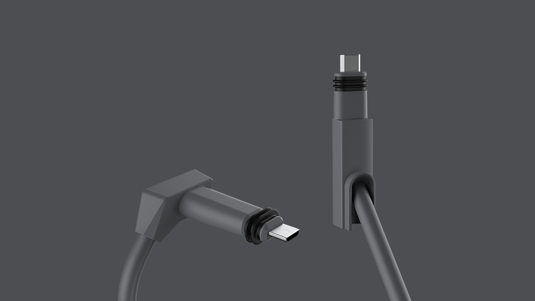
StarLink are bound by 60950-SELF and by the other cable rating standards (NEC, UL etc). If they put a consumer accessible RJ45 on the cable they also get limited by spec and limitations on RJ45, in particular a consumer connection to existing cabling (CAT5 and earlier) infrastructure. So far as I can make out that is where the 90W comes from. Using a proprietary connector removes the possibility of a consumer connection; either the cable has to be cut or the ends have to be ground off a USB-C socket (I intend to do the latter next). Presumably this is enough to remove the 90W/cable limit and, most likely, allow the router to put 120VA or more into the connector.

Please update us on how that goes.

@proavnerd
Copy link

Forgive me if this has already been covered. What if I'm just trying to splice the proprietary ends onto existing category cable? Can I just hack off both ends, terminate them with RJ45 plugs and connect to the length of cable routed through my walls? I presume this will work out just fine, assuming I'm terminating everything 568b. No injectors. Cat6 cable length under 150'. Anyone here done this before?

@WIMMPYIII
Copy link

Forgive me if this has already been covered. What if I'm just trying to splice the proprietary ends onto existing category cable? Can I just hack off both ends, terminate them with RJ45 plugs and connect to the length of cable routed through my walls? I presume this will work out just fine, assuming I'm terminating everything 568b. No injectors. Cat6 cable length under 150'. Anyone here done this before?

Yes that will work but keep in mind this will be more resistance then you are going to get with a stock 150ft cable with 2 plugs what you are talking about will be 6 plugs the 2 original and 4 between. And stranded rj45 plugs suck and passing power compared to solid conductors. The stock power supply in the router is already underpowered and undervolted for the power demand the dishy is putting on it. You are probably better off using k2 double blade cable connectors for you splices. But if you are staying under 150ft why not just use the stock cable?

@proavnerd
Copy link

Thanks for the reply. The distance is probably 60-80' end to end. While I have no doubt that power would pass better through gel bean K2 connectors, these are more for telephone signal. Data is susceptible to interference and other issues if the twist and shielding is not properly maintained.

You do ask a valid question though. Why not just use the stock cable? This is going on the roof of an ultra high end residence for internet failover. There are cables routed from the roof to the equipment racks already. Putting a new proprietary cable in place would require a tremendous amount of work, as silly as that sounds.

@jbowler
Copy link

jbowler commented Jan 29, 2023

This is going on the roof of an ultra high end residence for internet failover.

This gist is very much for people who are living on the edge. The RJ45 is limited to 90W, and then only with PSEs which meet the requirements of the IEC specs, the StarLink antenna requires more than that.

I just wouldn't do it that way. Run the infrastructure wiring as close as possible to the place the antenna will go, run power too. Put the router there; I'm guessing the installation uses the ethernet dongle because otherwise doing failover is, well, complex. (I have an installation with failover, but mine is the other way round; my local ISP is providing the failover for StarLink.)

Don't splice, or mod, the StarLink kit; just coil the 75ft cable up in the loft or wherever the router ends up. This is what I ended up doing, it worked just fine until the StarLink kit failed, but I own the house so I'm looking at getting rid of the router completely. Believe me when I sell this place that kind of stuff will be removed before the place even goes on the market (I live in the US.)

@proavnerd
Copy link

Tonight I replicated the setup at my client's house. The 75' proprietary cable was cut about 15' from the modem end. The signal path is now modem > Ethernet adapter > 15' of proprietary cable with RJ45 jack > 25' of Cat6 with plugs on both ends > 100' of Cat6 with jacks on both ends > 60' of proprietary cable with a plug on the end > dishy.

I'm running through a total of 200' of cable with 2 different cable skews and 3 junctions and it works fine. To validate my results, I pulled out the FLIR camera to take some photos of the connectors. The chatter here and elsewhere indicates that Starlink is using the modified USBC connectors to accommodate the amperage required by dishy. I expected the RJ45 junctions to be the weakest link in the chain and to see some heat generated there. That was not the case though. All the connectors are at room temperature, regardless of whether the heater is on or off.

The cables do appear to be about 3° warmer than room temperature, but that trivial amount of heat could still be residual from me coiling the cables after cutting them off the spool.

Reality here is that you could fill the ocean with things I don't know about how this actually works. How many watts does dishy actually draw when the heater is on? Is it different when the heater is in auto mode vs pre-heat? The cable I used isn't shielded. Does it matter? Should I have eaten that whole burrito? The list goes on forever. But I suspect that this the power supply is designed for the worst case scenario, taking into account voltage drop for the 150' proprietary cable and all the things (heater, servo motors, etc) operating at the same time. Likely for a more sustained period of time than will ever actually happen.

Should you do this? Absolutely not, as noted in the disclaimer at the top of the thread. Can you do this? Probably. Am I actually going to void the warranty on my client's backup satellite internet hardware just to make the cables pretty? -Yup.

@WIMMPYIII
Copy link

Tonight I replicated the setup at my client's house. The 75' proprietary cable was cut about 15' from the modem end. The signal path is now modem > Ethernet adapter > 15' of proprietary cable with RJ45 jack > 25' of Cat6 with plugs on both ends > 100' of Cat6 with jacks on both ends > 60' of proprietary cable with a plug on the end > dishy.

I'm running through a total of 200' of cable with 2 different cable skews and 3 junctions and it works fine. To validate my results, I pulled out the FLIR camera to take some photos of the connectors. The chatter here and elsewhere indicates that Starlink is using the modified USBC connectors to accommodate the amperage required by dishy. I expected the RJ45 junctions to be the weakest link in the chain and to see some heat generated there. That was not the case though. All the connectors are at room temperature, regardless of whether the heater is on or off.

The cables do appear to be about 3° warmer than room temperature, but that trivial amount of heat could still be residual from me coiling the cables after cutting them off the spool.

Reality here is that you could fill the ocean with things I don't know about how this actually works. How many watts does dishy actually draw when the heater is on? Is it different when the heater is in auto mode vs pre-heat? The cable I used isn't shielded. Does it matter? Should I have eaten that whole burrito? The list goes on forever. But I suspect that this the power supply is designed for the worst case scenario, taking into account voltage drop for the 150' proprietary cable and all the things (heater, servo motors, etc) operating at the same time. Likely for a more sustained period of time than will ever actually happen.

Should you do this? Absolutely not, as noted in the disclaimer at the top of the thread. Can you do this? Probably. Am I actually going to void the warranty on my client's backup satellite internet hardware just to make the cables pretty? -Yup.

How much more stress is this putting on the internal power supply and how will the dishy handle the voltage and amperage drop over a long period of time is the question.

@OleksandrSimakov
Copy link

Should I activate bridge mode if I want to use my own router in this setup?

@jbowler
Copy link

jbowler commented Jan 31, 2023

Should I activate bridge mode if I want to use my own router in this setup?

So far as I can see bridge mode is only required if IPv6 is required. If you are happy with the StarLink router as an IPv4 failover then I believe it should be possible to plug the dongle ethernet into the WAN port of a router with failover support but would result in triple NAT.

It seems much more simple to use "bypass" (i.e. bridge mode); having two routers just complicates the configuration and, indeed, the StarLink router wifi can't be switched off or hidden so that complicates the user experience as well. Bypass mode isn't perfect because the traffic still goes through two ethernet systems and, most likely, the MCU but I don't know if the antenna will boot without the ethernet connection; with PoE from a separate injector.

@OleksandrSimakov
Copy link

Should I activate bridge mode if I want to use my own router in this setup?

So far as I can see bridge mode is only required if IPv6 is required. If you are happy with the StarLink router as an IPv4 failover then I believe it should be possible to plug the dongle ethernet into the WAN port of a router with failover support but would result in triple NAT.

It seems much more simple to use "bypass" (i.e. bridge mode); having two routers just complicates the configuration and, indeed, the StarLink router wifi can't be switched off or hidden so that complicates the user experience as well. Bypass mode isn't perfect because the traffic still goes through two ethernet systems and, most likely, the MCU but I don't know if the antenna will boot without the ethernet connection; with PoE from a separate injector.

Thanks for insights. I would better stick to original Starlink router. For me there is no particular reason to use my own wi-fi router. Original one would suffice for my my needs

@jbowler
Copy link

jbowler commented Feb 1, 2023

For me there is no particular reason to use my own wi-fi router.

The terminology has evolved over the years and become confusing as a result. Both StarLink and my local ISP provide a bridge, in the form of the antennae, and then what is now called a router but used to be called a gateway is required afterward. Setting "bypass" mode on the StarLink router bypasses the gateway functionality of the router and means that another router (well, another gateway) is required.

Setting the StarLink router into bypass mode is not something anyone needs to do unless they already know then need to do it.

@morehardware
Copy link

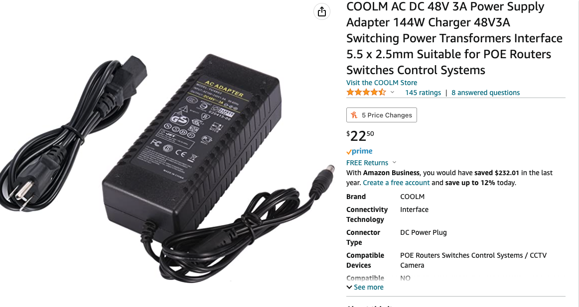
Ive had some difficulty converting my Starlink to 12 volts. I terminated my stock cable and built my own POE using the typical components described in youtube vids and Reddit forums confirmed to be working - 12 volt to 48V 3amp step up powersupply , Tycon POE injector. I put the Starlink in Bridge mode, hooked everything to a GL-Inet Beryl router wan port with the properly terminated ends (one swapped and the other not) and powered it up. The Starlink would attach for 30 seconds and then disconnect. I left it in this cycle for 3 hours and still no IP. I am mounting this on the roof of my van and my cable runs are extremely short. My gut feeling was that my power supply was too weak. I am plugging it into 15amp fused cigarette lighter socket. I bought a Mean well DDR120c and cranked it up to 50 volts and tried again but I am getting the same error. I was about to give up when I found a person using a 120volt to 48 volt stepdown transformer. I bought one and hooked it to a brand new Tycon POE Injector and it attached and acquired an IP successfully. There is obviously a difference in the 48 volts 3A coming from the 120 volt Power transformer and the Mean Well Converter at 48 volt 2.5 amps (besides the .5 amps) . The Mean Well has seemed to be a pretty dependable power supply for this MOD. I even tried to hook the Mean Well directly to a 12 car battery. Using 12 gauge wire all around. Any ideas about why my 12 volt to 48 volt system wont stay connected. but my 120 volt to 48 volt system works great?

![Screenshot 2023-02-01 at 9 18 33 PM](https://
Screenshot 2023-02-01 at 8 39 25 PM
user-images.githubusercontent.com/124229469/216238183-446fe523-4a24-413c-9be1-24a14363dda8.png)
IMG_0876

@jbowler
Copy link

jbowler commented Feb 2, 2023

I bought one and hooked it to a brand new Tycon POE Injector and it attached and acquired an IP successfully.

One potential weak point is the ethernet transformer chip used inside the PoE. There are a lot of these chips around but most of them only have a "30W" or "60W" capability. So far as I can see the transformer must be one of the newest ones designed for the highest power (class 8) 802.3bt; these have to support a continuous 99W at the PSE and I think that means 960mA/pair or 480mA/conductor. Even then, if the numbers are right, the transformer is being run over-powered. You seem to have the right Tycon injector, but they may use that box for lower power devices. Check what you have against the Tycon data:

https://www.tyconsystems.com/PoE-Injectors_c_172-1-2.html

(Search for the actual model number on that page.) I intend to double check the McCown and the Tycon (I have both) but the number given above for the McCown injector seems to correspond to a Pulse Electronics 30W (802.3at) transformer.

It would be a useful test to swap the old Tycon injector back without changing the setup to see if this has failed or not.

The likely failure point is startup of a cold dish. If "snow melt" is turned on this will draw maximum power. It's not clear to me that higher voltage helps here; heaters are normally purely passive so a higher voltage increases the current requirement in proportion. There are cheaper testers on Amazon that can test the actual power delivery:

https://www.amazon.com/gp/product/B08B46PMV3

But if the current goes over the limit something is likely to break... Check the output voltage of the two 48V supplies under load; at 2.4A. I do have one of those supplies (the first, switching, 3A/48V PSU) so I'm going to try to test that. It would be interesting to know which of them generates the lower voltage. The regular (non-switching) PSU will probably also have considerable ripple; who knows, that might help!

I couldn't work out which systems you have working. It seems the 48V/3A didn't work and neither did the Mean Well initially. They are both switching PSUs. Then there was a step down transformer system which seems to be the approach in your picture. Those are pretty hard to come by these days and the peak voltage one would deliver is almost 68V; the actual output depends on the voltage regulator inside the PSU, if there is one.

I've also encountered one 12V high current (10A or something like that) switching PSU which could not supply a low current (below 1A); it would just stop working. This seems to be a feature of high current PSUs, but it may be just a fault in the one I was trying to use.

In any case I have snow melt turned off; it's a persistent setting on the StarLink antenna (the dish). I might experiment with turning it back on but only if I have it powered through the StarLink kit (i.e. from the router). I want to find out what the actual current draw is first and I want to compare it with "preheat". There's no pre-heat only setting though, so if "snow melt" draws the kind of current people are suggesting it's pretty much useless without special ethernet transformers. I've seen 185W quoted, but that is almost twice what Oleg Kutkov quotes the router PSE as being able to output (120W):

https://olegkutkov.me/2022/04/10/initial-analysis-of-the-starlink-router-gen2/

It may be that the router has a slow turn-on or, indeed, maybe it is doing full 802.3bt with LLDP to negotiate power with the antenna? I'm still at the stage of needing to make test leads (SPX to RJ45) before I can find out more.

@torrmundi
Copy link

McCown 800-GIGE-APC transformer data sheet: https://drive.google.com/file/d/1CN1s0zdzvzn7WFps7vP6IgSC8o0_H3rV/view?usp=share_link
Dishpowa transformer data sheet: https://drive.google.com/file/d/10vF1zdiZoWkZGcegcOFoDLXQ6KCrkKwQ/view?usp=share_link

I blew out a Tycon POE-INJ-1000-WT transformer (unmarked part) and it shorted 1,2,4,5 to 7,8 and killed my dishy permanently. I could not find any fault in my wiring - I think the transformer chip simply overloaded.

@jbowler
Copy link

jbowler commented Feb 2, 2023

Note that Tycon make two of these:

https://www.tyconsystems.com/poe-inj-1000-wt Gigabit Passive PoE Injector/Splitter with LED Indicator. Injects or splits DC power on all 8 wires. 1245(+) 3678(-). Wire terminal connector. 2.25A. VIN=VOUT. Ubiquiti airFiber

https://www.tyconsystems.com/poe-inj-1000-wtx Gigabit Passive PoE Injector/Splitter with LED Indicator. Injects or splits DC Power on all 8 wires. 1278(-) 3645(+). Wire terminal connector. 2.25A. VIN=VOUT

The first (without the "x") is the standard 802.3af etc approach which puts the power across the transmit/receive pairs of a single channel; 12-36 (orange green) is the first channel used in half-duplex (4 conductor) pairs and 45-78 is the second channel for full duplex

The second one puts the positive on the middle four pins, 4536 (red, green pairs) and the negative on the outer (1278, orange brown) pairs. So plugging a WTx injector into any regular device with 4 pair PoE put a positive and a negative together on the pairs which normally supply either the positive or negative. On a diode protected PD this is no problem; the diodes route the positive or negative to the right place. On something with no diodes there is a short circuit that will instantly blow out the ethernet transformers in one or both ends (or a mixture of the two).

The StarLink is, I believe (DO NOT RELY ON THIS STATEMENT - check yourself) 1236+, 4578- Note that the WTs both put useable power on each half-duplex but that StarLink does not. The Tycon WT has 12(+)36(-), 45(+)78(-) and the Wtx has 12(-)36(+), 45(+)78(-) the latter corresponds to T-568A where green/orange (12, 36) are swapped relative to T-568B. Whereas StarLink has 12(+)36(+) 78(-)45(-) One half-duplex pair-of-pairs is wired positive, the other negative. Presumably there is some benefit to this...

The obvious protection is to wire four IN4005 diodes in the right direction from the PSU to the center taps of the transformers in the PoE injector. That protects both ends (PD and PSE) except that the PD might end up with positive and negative supply rails swapped. Better is to protect the PD, but that increases the power requirement at the PSE injection point (until if the diodes are in the PSE, before the injection point).

EDIT (important): diodes in the PSE will not help. The diodes have to be in the PD to prevent miswiring at the PSE or PD end from connecting the PSE + directly to the PSE -. Given that @OleksandrSimakov apparently fried at least the PSE with the Tycon WTX it certainly sounds like the Dish does not have protection diodes. Aargh; they should have put protection diodes in and gone with a higher voltage; at least 57.6V. the diodes will output a small number of watts, but only if pre-heat or snow-melt is on when, surely, it doesn't matter...

@morehardware
Copy link

morehardware commented Feb 2, 2023 via email

@torrmundi
Copy link

torrmundi commented Feb 3, 2023

I purchased a POE Tester (Noyafa NF488S) from Amazon. There were issues:

  1. cannot test Starlink non-standard 4PPoe
  2. does not measure standard 4PPoe power correctly
  3. does not indicate positive or negative voltages on 4PPoe wires

Results:
With 4pair PoE injecter, Tycon, 1,2,4,5 (V+) 3,6,7,8 (V-)

  • the tester showed midspan with all 8 lines as active, but not which are positive or negative. Voltage was measured.
  • the tester, with no PD connected, showed that 15W was being dissipated
  • the tester, with a PD connected (Peplink Max BR1 Mini), showed that 19W was dissipated

With Starlink cable, midspan, 1,2,3,6 (V+) 4,5,7,8 (V-)

  • "unknown" was displayed, and no lines as active. Voltage was measured.
  • 0.0W power measurement
  • The cable was able to be used for data transmission, with the tester inserted midspan

@jbowler did you use the TRENDnet Inline PoE Tester, TC-NTP1 successfully?

@morehardware
Copy link

morehardware commented Feb 4, 2023 via email

@WIMMPYIII
Copy link

Didn't even know there was such an instrument. I was thinking that another way to decrease the power draw of Dishy besides turning snow melt off would be to disconnect the motors . I plan to flat mount it anyways . It’s works very dependably on the 120 volt to 48 volt transformer direct to Tyco Poe. Seems the Poe is working. Maybe there are different qualities of Poe that may only work with certain “types” of 48 volt dc power. I’m puzzled why 48 volts doesn’t work with 12 volt sources switch the TYCO in my situation and works for others. Get Outlook for iOShttps://aka.ms/o0ukef

________________________________ From: torrmundi @.> Sent: Friday, February 3, 2023 3:04:39 PM To: torrmundi @.> Cc: Comment @.>; Manual @.> Subject: Re: darconeous/rect-starlink-cable-hack.md @torrmundi commented on this gist.
________________________________ I purchased a POE Tester (Noyafa NF488S) from Amazon. There were issues: 1. cannot test Starlink non-standard 4PPoe 2. does not measure standard 4PPoe power correctly 3. does not indicate positive or negative voltages on 4PPoe wires Results: with 4pair PoE injecter, Tycon, 1,2,4,5 (V+) 3,6,7,8 (V-) * the tester showed midspan with all 8 lines as active, but not which are positive or negative. Voltage was measured. * the tester, with no PD connected, showed that 15W was being dissipated * the tester, with a PD connected (Peplink Max BR1 Mini), showed that 19W was dissipated with Starlink cable, midspan, 1,2,3,6 (V+) 4,5,7,8 (V-) * "unknown" was displayed, and no lines as active. Voltage was measured. * 0.0W power measurement * The cable was able to be used for data transmission, with the tester inserted midspan @jbowlerhttps://github.com/jbowler did you use the TRENDnet Inline PoE Tester, TC-NTP1 successfully? — Reply to this email directly, view it on GitHubhttps://gist.github.com/8c7899c4d2f849b881d6c43be55066ee#gistcomment-4459194 or unsubscribehttps://github.com/notifications/unsubscribe-auth/A5TZOXIDUMW7QZVRA4RYSMDWVWFIRBFKMF2HI4TJMJ2XIZLTSKBKK5TBNR2WLJDHNFZXJJDOMFWWLK3UNBZGKYLEL52HS4DFQKSXMYLMOVS2I5DSOVS2I3TBNVS3W5DIOJSWCZC7OBQXE5DJMNUXAYLOORPWCY3UNF3GS5DZVRZXKYTKMVRXIX3UPFYGLK2HNFZXIQ3PNVWWK3TUUZ2G64DJMNZZDAVEOR4XAZNEM5UXG5FFOZQWY5LFVEYTCNBSGQ2TCMRTU52HE2LHM5SXFJTDOJSWC5DF. You are receiving this email because you commented on the thread. Triage notifications on the go with GitHub Mobile for iOShttps://apps.apple.com/app/apple-store/id1477376905?ct=notification-email&mt=8&pt=524675 or Androidhttps://play.google.com/store/apps/details?id=com.github.android&referrer=utm_campaign%3Dnotification-email%26utm_medium%3Demail%26utm_source%3Dgithub.

Did you compare exact voltage and amperage numbers as well as fluctuation between the 12 vs 120 converter? My guess is the 12 to 48 is not holding high enough volts or amps for the dishy's power regulator. And if you are running close to the edge on that power regulator that potentially creates more heat and stress.

@jbowler
Copy link

jbowler commented Feb 4, 2023

@jbowler did you use the TRENDnet Inline PoE Tester, TC-NTP1 successfully?

@torrmundi: I haven't received it yet, it should come early next week. I did also order one of the NF488 testers, possibly a slightly different revision since mine is NF-488 not NF-488S. Mine seems to work better than yours; I've done limited testing and it correctly identifies 802.3af and at, mode A (4 pairs, channel 1) and AB (both channels). It doesn't support 802.3bt and plugged into a bt switch it reports it as 802.3at with "4 pairs". The power rating when used with a PD on the PoE "Out" RJ45 seems credible. I suggest testing the accuracy of the DC out and DC in ports if you have a load tester (not that they are necessarily that accurate ;-). It's certainly a return if that doesn't work. On mine the "loopback" port doesn't seem to work but that might be my managed switches rejecting a loopback connector.

I believe the polarity of the channels is reported by the voltage; plugged into a switch with 802.3af I get a negative voltage but into the 802.3bt capable switch the voltage was positive. It would be much better if the pins were displayed with "+", "-" or " " underneath. I haven't tested with passive injectors yet; I've only had the tester 12 hours.

With Starlink cable, midspan, 1,2,3,6 (V+) 4,5,7,8 (V-)

I'm not surprised that gave "unsupported"; channel 1 is (all) positive and channel 2 negative. I haven't hacked the test leads for StarLink together yet but my default would be to fabricate swapped 36/45 pairs at both sides then I would expect to see the tester report something; the swapping makes the tester see 1,2,4,5(V+) 3,6,7,8(V-) which corresponds to the POE-INJ-1000-WT that I have and 802.3a[ft] modes A and B. BTW Tycon sells these injectors direct for $10 each and currently has 2683 (or so) in stock. Shipping is $6 USPS; cheaper than anything on Amazon.

As for the McCown I couldn't access your links; Google Drive shareable links normally work just fine for me so I think they might be something else (like the thing on the address bar when a shareable link is created?) I did get home and eyeball my own McCown 800-GIGE-POE-APC (i.e. the Cat5e APC version, not the Cat6 APC version). The transformer is a LINK-PP LP6062ANL:

http://www.link-pp.com/?product/201408082292.html

From the datasheet the current rating (for PoE) is "720mA continuous over 4 pairs", further described on the second page as "[e]xceeds 802.3at requirements with up to 720mA DC supply current over 2 or 4 pairs". This is better than the Pulse Electronics H6062NL component which it claims it's a clone of:

https://productfinder.pulseelectronics.com/part/h6062nl

The datasheet for that states, "DC CURRENT/VOLTAGE RATING 350mA MAX @57V (CONTINUOUS)", I assume that is per pair so a total current delivery/return of 700mA for 39W. So this is not an 802.3bt capable part. The maximum using 60V would be under 45W at the PSE (less at the dish of course).

I assume the Tycon parts, despite being so cheap, are using 802.3bt capable transformers; the input is up to 2.25A at 80V which means that can handle 180W at the PSE. I haven't worked out how to pop the Tycon box open yet but I think I will use the McCown for testing since the jumpers allow testing on individual pairs and I have Snow Melt off, then use a Tycon and probably order a couple more for disassembly/testing.

@jbowler
Copy link

jbowler commented Feb 4, 2023

@morehardware:

Maybe there are different qualities of Poe that may only work with certain “types” of 48 volt dc power. I’m puzzled why 48 volts doesn’t work with 12 volt sources switch the TYCO in my situation and works for others.

I find it very puzzling too. I second @WIMMPYIII's recommendation to check the voltages under load in both cases. The NF-488 has DC barrel jacks for testing a PSU connected to "DC In" and a powered device, in this case the Tycon PSE, connected to "DC Out". It can also be tested using two Tycons back-to-back (POE IN/OUT connected together) and a load tester on the "DC IN/OUT" of the second, but load testers may be more difficult because of the higher powers involved; you need to know the approximate current load in the failing system first, or just wing it and hope you don't destroy the load tester.

You are chaining a "boost" converter (12->48V) to one or more "buck" converters in the dish/antenna. The latter converts the 48V back to electronics levels, typically 3.3V or 5V these days. The snow melt may also use a buck or even boost converter but is more likely IMO to just use the original 48V switched on and off as required (possibly using PWM). There should be no problem with any of this, e.g:

https://electronics.stackexchange.com/questions/231668/chaining-buck-converters

The connection, via the PSE and the ethernet transformers, ends up being just a pair of conductors stranded out of four of the eight 24AWG Cat5e conductors each. There's no net inductance in the leads and relatively small capacitance from the high frequency RC filters (resistor->capacitor->ground) used to remove spurious in-phase signals on the conductor pairs.

Buck and boost circuits are pretty much identical, e.g. see the circuit diagrams here:

https://en.wikipedia.org/wiki/Buck%E2%80%93boost_converter

You could try checking the capacitor on the output side of your boost converter. It has to be sufficient to support the peak load current but, since it is feeding into a boost converter which has its own output capacitance excessive ripple may only cause a drop-out intermittently. To test a system under load put an AC voltmeter across the output of the boost converter. Better use a multi-meter that supports display of AC and DC voltage at the same time (Flukes do, others do too). Best is to find peak-peak of the AC but RMS x 1.4 (sqrt(2)) is probably enough for this. If the AC can reduce the DC below some critical voltage the buck converter on the other end might be unable to keep up the output.

It's also possible to use a Fluke or other multimeter with "fast min-max" to try to detect the minimum voltage over an extended period, but I don't know if that would be fast enough to see a significant dropout in the voltage.

@WIMMPYIII
Copy link

I ordered this 10-20VDC to 52v booster i will try when i get some free time.
https://www.aliexpress.us/item/3256803129874148.html?gatewayAdapt=glo2usa4itemAdapt&_randl_shipto=US

@morehardware
Copy link

morehardware commented Feb 5, 2023 via email

@jbowler
Copy link

jbowler commented Feb 6, 2023

More on the NF-488 and also on the StarLink router/antenna, though I will enter that separately.

My NF-488 is one of these:

https://www.amazon.com/dp/B08GK7CGGD

I've done more extensive testing including, finally, putting it between the router and the dish. I did see the strange wattage behavior @torrmundi reported but I still find the device useful. No doubt one of the Fluke testers would be a lot better but that is comparing something that costs $36 with something that costs $1400. I hope to receive the TRENDNet tester on Monday and that may better handle the protocol stuff than the NF-488 because supposedly it recognizes 802.3bt.

On the NF-488 most of the stuff works just fine; cable continuity is clear and precise, though it doesn't recognize a cross-over cable (it does correctly display the cross-over). DC power tests seems fine, as I said before. The loopback is apparently non functional; I can here a relay clicking on when I activate it but none of the switches I've tried give any indication of a loopback.

The device uses different RJ-45 jacks for different tests, which is ok, however the PoE tests use the same two ports and this can create wackiness; entering the PoE test mode starts the "inline test", pressing "OK" does the PSE test. Pressing OK during an "inline" test, i.e. while a PD is connected to the PoE out jack, somtimes, often, messes things up. It's not just the tester that gets messed up, well, probably it's not the tester at all, but the PSE and the PD can end up behaving weirdly.

The tester displays a "wattage" in both PSE test and in-line mode. In the PSE test mode it's not clear what the wattage is, maybe it's some guess at the PSE supported wattage because sometimes the number is very high even though there is no load (other than the tester). E.g. 8.4W with one PSE (consistently) but only a couple of watts with others. The number is not useful.

The tester correctly identifies 802.3af and 802.3at PSEs. If correctly detects Mode A and Mode B, though it incorrectly calls Mode A (power on the data pairs) "End Point" and Mode B (power on the "spare" pairs) MidPoint. It seems from the Amazon page that the TRENDNet uses the same incorrect terminology though it does also include the Mode. It doesn't identify endpoint or midpoint PSEs, how could it? It also identifies "4-pair" PSEs and this is how 802.3bt supplies are listed (unless they swap into af or at mode).

With inline testing the power seems approximately right at least with the range of splitters I have; I don't have an 802.3bt capable splitter or, for that matter, a device that I can test with (except, maybe, the StarLink antenna). I get a credible, higher, value from the tester compared to what I get from my load. All my test splitters are buck converters; the test load gives me about 80% of the tester, which is reasonable for a cheap buck converter.

The NF-488 powers off after a while. This is fine because inline test just keeps on working; the NF-488 seems to appear as a purely passive implementation so it looks, so far as I can tell, like one of the back-to-back RJ-45 female-female connectors.

My best guess as to how the PoE inline measure is done is that the device uses a single Hall effect sensor (like in a DC current clamp ammeter). These devices have the problem of needing to be zeroed and there is no zero interface in the NF-488. They are also not very accurate at low current; 1W at 50V is only 20mA. It is conceivable that the device includes an ethernet transformer, I haven't tested whether it does, but given the apparently low accuracy this doesn't seem likely.

If my assumption is correct the NF-488 requires a "standard" arrangement of PoE on either one or both Ethernet channels. The StarLink trick of putting positive on channel 1 and negative on 2 will just cancel out in the power sensor and cause the NF-488 to see an unconnected PSE. I tested StarLink using reversed green/blue pairs and I got credible (though very interesting) results from the NF-488.

I can't wait 'til Monday when I get the TRENDNet 802.3bt capable tester. Almost as good as getting an ActionMan with an FGMP-15.

@WIMMPYIII
Copy link

This is great stuff. Thank you. I will measure the amp draw on both the power supplies ( working and non working) to try to discern the difference . I found this in a Reddit thread that is also discussing the inadequacies of third party power supplies to Starlink . This 12 volt one seems to work better than the Mean Well. DC-DC Converter Module Boost DC Step Up Voltage Regulator CV Stabilizer Power Supply Module 10-60V to 12-97V 1500W 30A https://a.co/d/8AmKplF This worked where a mean well did not.

________________________________ From: WIMMPYIII @.> Sent: Saturday, February 4, 2023 11:29:16 AM To: WIMMPYIII @.> Cc: Comment @.>; Manual @.> Subject: Re: darconeous/rect-starlink-cable-hack.md @WIMMPYIII commented on this gist.
________________________________ I ordered this 10-20VDC to 52v booster i will try when i get some free time. https://www.aliexpress.us/item/3256803129874148.html?gatewayAdapt=glo2usa4itemAdapt&_randl_shipto=US — Reply to this email directly, view it on GitHubhttps://gist.github.com/8c7899c4d2f849b881d6c43be55066ee#gistcomment-4459920 or unsubscribehttps://github.com/notifications/unsubscribe-auth/A5TZOXKZP77LQFWYUDVSGJDWV2UY3BFKMF2HI4TJMJ2XIZLTSKBKK5TBNR2WLJDHNFZXJJDOMFWWLK3UNBZGKYLEL52HS4DFQKSXMYLMOVS2I5DSOVS2I3TBNVS3W5DIOJSWCZC7OBQXE5DJMNUXAYLOORPWCY3UNF3GS5DZVRZXKYTKMVRXIX3UPFYGLK2HNFZXIQ3PNVWWK3TUUZ2G64DJMNZZDAVEOR4XAZNEM5UXG5FFOZQWY5LFVEYTCNBSGQ2TCMRTU52HE2LHM5SXFJTDOJSWC5DF. You are receiving this email because you commented on the thread. Triage notifications on the go with GitHub Mobile for iOShttps://apps.apple.com/app/apple-store/id1477376905?ct=notification-email&mt=8&pt=524675 or Androidhttps://play.google.com/store/apps/details?id=com.github.android&referrer=utm_campaign%3Dnotification-email%26utm_medium%3Demail%26utm_source%3Dgithub.

I wonder how much heat these things produce at max dishy power? Is the fan needed with this level of draw? And what are people putting this into? An enclosure?

@jbowler
Copy link

jbowler commented Feb 6, 2023

I tested the StarLink router PoE using the NF-488 PoE (et al.) tester which I described in my previous comment. I have the tester inserted into an Ethernet Dongle cord; this was simply the quickest way of doing it. I'm not going to describe how to put the tester inline here, it seems off topic, suffice to say that I took a mighty cleaver to the Ethernet Dongle cord, chopped it in two, sewed two shielded Cat5e jacks on the exposed ends and put the tester between them. The Cat5e jacks have the blue/green pairs reversed; so pins 4,5 are swapped with pins 3,6 (keep the striped/solid conductors alternating, though it doesn't matter much).

When this is done the NF-488 correctly recognizes the StarLink router as providing "4-pair" PoE and reports voltages and "wattages" which I believe. The "wattage" may well actually be a VA but it doesn't matter with regard to the load on the connections.

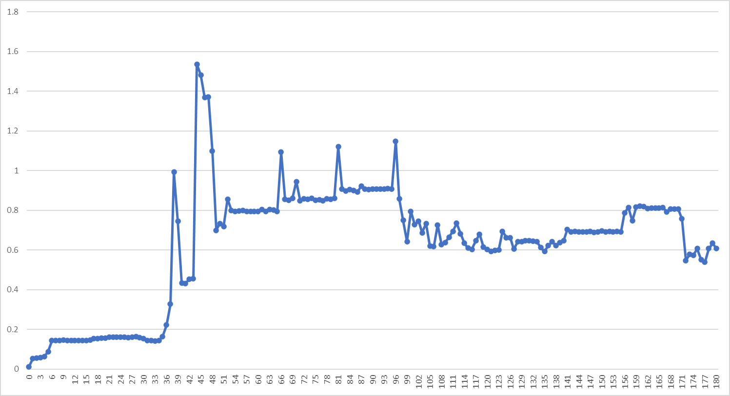
The reported wattages vary between around 20W and 66W. I don't know the averaging period, indeed these might be instantaneous values, but they consistently stick within that range and the voltages vary in proportion; pretty much a peak of 48V down to 47V (this is at the PSE of course).

When used as a tester for the router PSE, i.e. with the dish disconnected, the NF-488 cannot identify the PSE. It ends up saying that it is non-standard. During these tests the router maxes out at 2.8V; i.e. with the dish disconnected it supplies no power indicating that it is an active PSE. It may be 802.3bt, as Oleg KutKov suggested, but with wacky wiring; it may even be doing LLDP. This is part of the reason I want to test the setup with the TRENDNet product which, supposedly, handles 802.3bt.

With just the antenna connected and a break-out cable I was able to find the connectivity between the pairs and, most likely, a fault in my StarLink antenna. I measured the Ethernet Transformer resistances. This is across the StarLink 75ft cable, so the resistances I say included the cable. Three of the four pairs sat at around 7.5ᘯ, the fourth pair (78, brown) was an open circuit. I then measured the resistances between the windings. These were around 3.5ᘯ for the positive and negative pairs and around 33kᘯ between those pairs. It turned out that the brown-white connection is broken somewhere; so the brown is continuous and that supplies the DC power (so the negative is over three conductors, not four) but the second ethernet channel is broken. The StarLink antenna debug data backs this up:

{ "dish": { ... "ethSpeedMbps": 100,

There is no other information anywhere that I can see showing that the ethernet is half duplex! Nevertheless that is specific to my, broken, StarLink system. EDIT: it was my error, I had not completely punched down the brown-white wire in the Cat5e jack. I'm back to "ethSpeedMbps": 1000 now.

It is absolutely clear that the PD, the antenna, is an active PoE device. It's implementing some protocol, perhaps 802.3bt with modified wiring. It also doesn't have diode protection against reverse circuit; I was using a Fluke 183 to do the resistance tests and it did not show a diode in the wiring. The router does not implement 802.3af or 802.3at; I'm confident that the tester can detect that and my test was independent of the broken dish conductor/ethernet transformer.

@jbowler
Copy link

jbowler commented Feb 7, 2023

A quick note on the TRENDnet TC-NTP1:

https://www.amazon.com/dp/B08B46PMV3

It measures the two ethernet channels separately, so when I put it in my system with blue/green pairs swapped it gets mismatched channels. It still works, but it breaks the StarLink antenna data connection; my router reports that the WAN cable is not connected. It does seem to be more accurate on wattage than an inline NF-488 (compared to the DC port measurements from the NF-488). It would probably not work at all with the McCown setup (because the two channels have no net current flow each). Bottom line is it is probably not the right product for this thread. It does apparently manage to identify 802.3bt, however it is not able to get the StarLink router to offer power most likely because it draws power from the PSE and the router only offers 2.8V or so at startup.

@torrmundi
Copy link

torrmundi commented Feb 7, 2023 via email

@morehardware
Copy link

morehardware commented Feb 7, 2023 via email

@jbowler
Copy link

jbowler commented Feb 7, 2023

@morehardware: Would it not be because the Dishy always engages the motors when you plug in as it boots up.

This is my best guess too. My second best guess is that it fires up the antenna array trying to find all the satellites. If it is the motors that is an inductive load and it is pretty much certain that the NF-488 is outputting VA, not W. This doesn't matter from the point of view of frying the ethernet transformers; that depends on the amperage, but the currents I've seen are well within the range the Tycon supports. Since the peak seems to happen around 30s after boot it may be the cause of your problem.

I can't find any wisdom online about using a switching PSU with an inductive load. There is lots of stuff about switching the load itself of course, but I'm sure the antenna is set up to deal correctly with that. I also don't know from my experiments what the true maximum load, minimum voltage and maximum amperage are. Today's exciting job is to wire one of these into the power supply:

https://www.amazon.com/dp/B0BGPG9NVR

This has minimum/maximum readouts with sub-second sampling; apparently below 0.4s. It's main display is an "instantaneous" reading, actually the average over the last 0.4s but it retains averages since start-up as well.

Sign up for free to join this conversation on GitHub. Already have an account? Sign in to comment