Skip to content

Instantly share code, notes, and snippets.

@darconeous
Last active December 7, 2024 17:45
Show Gist options
  • Save darconeous/8c7899c4d2f849b881d6c43be55066ee to your computer and use it in GitHub Desktop.
Save darconeous/8c7899c4d2f849b881d6c43be55066ee to your computer and use it in GitHub Desktop.
Hacking the Rectangular Starlink Dishy Cable
@torrmundi
Copy link

Agreed; I should have shielded cable outside, terminating the ground at the lightning surge protection device. Further cabling may be shielded, but should not be allowed to terminate to ground again.

@WIMMPYIII
Copy link

WIMMPYIII commented Dec 7, 2022 via email

@WIMMPYIII
Copy link

Agreed; I should have shielded cable outside, terminating the ground at the lightning surge protection device. Further cabling may be shielded, but should not be allowed to terminate to ground again.

Any new updates on your situation? Do you have a new dishy on the way?

@torrmundi
Copy link

torrmundi commented Dec 16, 2022 via email

@OleksandrSimakov
Copy link

OleksandrSimakov commented Jan 14, 2023

Can I use the setup on the diagram, but with the original Starlink router? The aim in my case is just to extend the cable. I am asking because I thought that there is already one POE (48V) in original Starlink router and what would happen if I bring the Tycon one (52V powered) right after it. Would that work?

C725C2A2-AAB8-4A4F-BA6D-0C4A77C95910

@WIMMPYIII
Copy link

WIMMPYIII commented Jan 14, 2023

Can I use the setup on the diagram, but with the original Starlink router? The aim in my case is just to extend the cable. I am asking because I thought that there is already one POE (48V) in original Starlink router and what would happen if I bring the Tycon one (52V powered) right after it. Would that work?

C725C2A2-AAB8-4A4F-BA6D-0C4A77C95910

Yes you can. But I think dishypowa or Mcown injector is a better option.

@OleksandrSimakov
Copy link

Thanks

@WIMMPYIII
Copy link

Thanks

With dishypowa or the Mcown you are not crossing pairs back and forth you are just terminating standard 568b.

@OleksandrSimakov
Copy link

OleksandrSimakov commented Jan 17, 2023

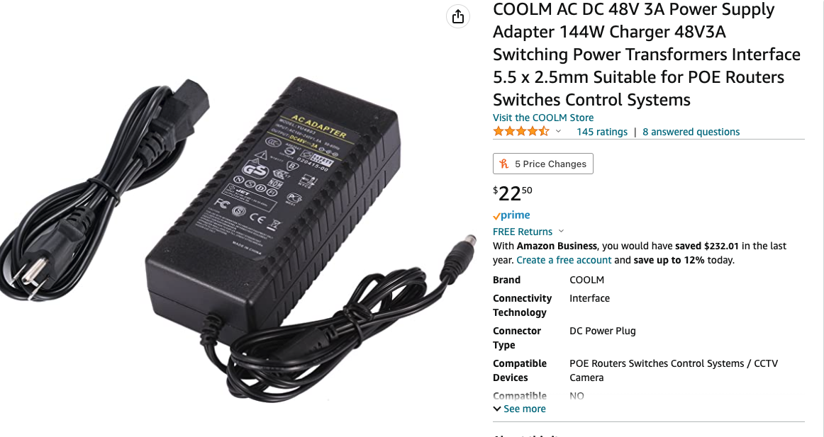
After the setup is done as described (with blue-green swaps on cables to poe and power adapter 52v as recommended), Starlink router lamp is off and the app says „connect to starlink wi-fi“. What could be the reason? When I remove poe and power adapter and connect straight back to dishy the Starlink router lamp becomes on, but the app says starlink is disconnected (probably because of lack of poe). Cat5e extension length is 180‘ and original cable 75‘.
What is I try to use a standard passive poe?

@WIMMPYIII
Copy link

After the setup is done as described (with blue-green swaps on cables to poe and power adapter 52v as recommended), Starlink router lamp is off and the app says „connect to starlink wi-fi“. What could be the reason? When I remove poe and power adapter and connect straight back to dishy the Starlink router lamp becomes on, but the app says starlink is disconnected (probably because of lack of poe). Cat5e extension length is 180‘ and original cable 75‘. What is I try to use a standard passive poe?

What power supply are you using? What is it's specs. What injector are you using and what are it's max throughput specs?

@OleksandrSimakov
Copy link

https://www.amazon.com/dp/B07WL7R26Z
and
https://www.amazon.com/dp/B07P8WNWFD
I plug router cable to injector‘s socket „data and poe“ and dishy cable to the socket „data“ and the adapter starts to make beep sound each several seconds.

@WIMMPYIII
Copy link

The dishy should be the poe port the router data only.

@OleksandrSimakov
Copy link

Your question revealed my mistake. I used poe with a different pinout. Not this one https://www.amazon.com/dp/B07P8WNWFD
But this one
FFEEF693-00C3-4A9B-B267-D2C8C5B3E809

Can I swap the wires to go with this one or I need to buy the exact one above?

@WIMMPYIII
Copy link

As long as you get the right + - on the right wires you should be fine. But if you mess it up it can definitely fry the dishy.

@WIMMPYIII
Copy link

Your question revealed my mistake. I used poe with a different pinout. Not this one https://www.amazon.com/dp/B07P8WNWFD But this one FFEEF693-00C3-4A9B-B267-D2C8C5B3E809

Can I swap the wires to go with this one or I need to buy the exact one above?

Did you get it working?

@OleksandrSimakov
Copy link

Your question revealed my mistake. I used poe with a different pinout. Not this one https://www.amazon.com/dp/B07P8WNWFD But this one FFEEF693-00C3-4A9B-B267-D2C8C5B3E809
Can I swap the wires to go with this one or I need to buy the exact one above?

Did you get it working?

Not with this poe I mentioned above.
Will wait till a proper one.
At least the dishy is not fried. Works with original cable

@jbowler
Copy link

jbowler commented Jan 23, 2023

This seems to be a more detailed breakdown of the pinouts; it's a breakdown of the ethernet dongle but there is a lot of information about the power and a little more in the comments. Of course I don't know whether any of it is correct:

https://olegkutkov.me/2022/03/07/reverse-engineering-of-the-starlink-ethernet-adapter/

The two things I find significant (if, of course, they are correct) is that the G O pairs are doubled on the pins but the B BR pairs are not. The author suggests that power is not present on the B BR pairs; the diagram of the pinout states this, and it would make sense, sort of, to do it that way.

The second is @POE_Guys comment about the snow melt; search for "185W". That's what happened to me a couple of days ago; it started snowing and something got fried. Once again I don't know of the 185W figure is correct (I haven't looked at the router teardown to see if there is any chance it can deliver that) but it would seem to make sense to put a pretty damn powerful PoE right next to the antenna.

EDIT: is the data wiring half-duplex? Back in the day we used to run two ethers down one set of 4 pairs using a splitter; the green-orange pair gave the first connection, the blue-brown pair the second (which a splitter had to map back to green-orange on the output). It would make sense not to duplicate the wires for the real data lines, and half duplex is more than enough for StarLink.

@jsharper
Copy link

EDIT: is the data wiring half-duplex? Back in the day we used to run two ethers down one set of 4 pairs using a splitter; the green-orange pair gave the first connection, the blue-brown pair the second (which a splitter had to map back to green-orange on the output). It would make sense not to duplicate the wires for the real data lines, and half duplex is more than enough for StarLink.

It's true, 10mbps and 100mbps only use two pairs. But for 1000mbps (gige), you need all four pairs. Starlink definitely needs gige and uses all four pairs. (Note - when using 2 pairs for 10 or 100, it's still capable of full duplex; one pair is for data flowing in each direction)

@jbowler
Copy link

jbowler commented Jan 23, 2023

But for 1000mbps (gige), you need all four pairs.

Half duplex 1000mps is apparently part of the gigabit standard:

https://networkengineering.stackexchange.com/questions/34196/has-half-duplex-gigabit-ethernet-ever-been-used

Gigabit is 1000mbps per double pair, so full duplex is 1000mbps download and 1000mbps upload (on the other pair). StarLink control both ends of the cable; one in the antenna, the other the router, so they could implement half duplex sharing the 1000mbps between upload and download and they would have well over their approximately 200mbps+20mbps peak. Even for business with 200+200 that's still way less than 1000.

The only way to know is to split out the mangled USB-C connectors using a couple of breakouts and experiment. What happens if the antenna is plugged directly into a managed switch? A managed switch is the easiest way I know to debug the other end of an ethernet cable because the management UI says precisely what is happening.

This is what I would actually like to do; my system is fried and I'm on hold with StarLink support (perhaps for ever). I don't know if the antenna, the router, or the cable is the problem but regardless given the number of reports of this problem on r/StarLink it would be nice to remove all but the antenna. All the same it isn't clear to me from this conversation or others what results people have got, if any, from plugging the StarLink ethernet into a managed switch; does it work, is it full duplex and is it reliable?

The negotiation is apparently half-duplex:

https://en.wikipedia.org/wiki/Gigabit_Ethernet

So another possibility is that the antenna negotations the download side to the BL-BR pairs, where I'm guessing the transmission is more reliable, and puts up with failures on the duplicated OR-GR pairs.

Yet BL and GR have been swapped; that's weird too. I guess it means that, in fact, each half of the duplex has one pair of lines which are doubled and another which are single?

@jbowler
Copy link

jbowler commented Jan 23, 2023

The whole shebang looks like 802.3bt, as someone observed on Oleg's teardown. It's easy to find with a breakout; just look for "rsig" across the various pairs. The way the wiring works:

https://www.microsemi.com/document-portal/doc_view/136209-next-generation-poe-ieee-802-3bt-white-paper

The rsig connects each of the pair of pairs across which the power must be delivered. The catch is that there is a bridge rectifier in front of each rsig. If the pairs are not matched correctly in the "dual signature" mode bad things are likely to happen. Otherwise, single signature, it should be possible to make any arbitrary pair of the pairs positive and the other pair of pairs negative and, because of the two bridge rectifiers, it seems to me positive will end up on positive and negative on negative from both supply channels. This is assuming the power source on the other end has cojoined positive and cojoined negative.

The first test is to check the antenna rsig to see if it is single signature or dual signature or, maybe, neither (in which case ignore all this post). In "single" it's not possible (I think) to deduce which pairs connect to which bridge rectifier. Indeed if the circuit is rearranged it is easy to see that there are no bridge rectifiers as such; just a pair of diodes to connect each pair to either positive or negative as appropriate (but I guess that is a bridge rectifier, just a four lane bridge ;-)

The transformers burn out if the individual wires from the pairs are mis-wired. This puts the full 48V with it's massive current capability across just a couple of small transformers (well, 50% of the time I think).

So far as I can see any 802.3bt injector should work, such as this one:

https://www.amazon.com/dp/B08D3CKBMS

I.e. I'm saying that the actual polarity does not matter if it really is 802.3bt and, if it is single signature, neither should the polarity on any pair just so long as two are positive and two negative.

@WIMMPYIII
Copy link

The whole shebang looks like 802.3bt, as someone observed on Oleg's teardown. It's easy to find with a breakout; just look for "rsig" across the various pairs. The way the wiring works:

https://www.microsemi.com/document-portal/doc_view/136209-next-generation-poe-ieee-802-3bt-white-paper

The rsig connects each of the pair of pairs across which the power must be delivered. The catch is that there is a bridge rectifier in front of each rsig. If the pairs are not matched correctly in the "dual signature" mode bad things are likely to happen. Otherwise, single signature, it should be possible to make any arbitrary pair of the pairs positive and the other pair of pairs negative and, because of the two bridge rectifiers, it seems to me positive will end up on positive and negative on negative from both supply channels. This is assuming the power source on the other end has cojoined positive and cojoined negative.

The first test is to check the antenna rsig to see if it is single signature or dual signature or, maybe, neither (in which case ignore all this post). In "single" it's not possible (I think) to deduce which pairs connect to which bridge rectifier. Indeed if the circuit is rearranged it is easy to see that there are no bridge rectifiers as such; just a pair of diodes to connect each pair to either positive or negative as appropriate (but I guess that is a bridge rectifier, just a four lane bridge ;-)

The transformers burn out if the individual wires from the pairs are mis-wired. This puts the full 48V with it's massive current capability across just a couple of small transformers (well, 50% of the time I think).

So far as I can see any 802.3bt injector should work, such as this one:

https://www.amazon.com/dp/B08D3CKBMS

I.e. I'm saying that the actual polarity does not matter if it really is 802.3bt and, if it is single signature, neither should the polarity on any pair just so long as two are positive and two negative.

No, it absolutely does not work!
You may be able to get by with it if you turn the heater off and never use heat, if you can even get it to boot. But if its mounted 150ft somewhere you probably don't want to go without heat.
It is not nearly enough power to handle the load spikes it demands. You need more than 100w if you are going to go over 150ft.
Not all stock routers are 100% stable at 150ft with the 48v internal power unit when it is freezing out.
I think starlink is pushing it very close to the threshold of what awg 23-24 stranded pairs can handle.
Slightly higher voltage takes a little stress off the cable too so depending on your distance it should be at least 52v or higher going over the 150ft mark.
That puts you ahead of the cable failure statistics. The last thing you want is the cable close to the edge of failure on a tree or tower or burried 150+ feet out in the yard or field.

@jbowler
Copy link

jbowler commented Jan 23, 2023

You may be able to get by with it if you turn the heater off and never use heat, if you can even get it to boot. But if its mounted 150ft somewhere you probably don't want to go without heat.

If I do this I will be mounting the PoE injector about 3ft cable length from the antenna. I could probably even drop it to 1ft. The data-only side of the PoE will then sit approximately 18ft from the router (a Synology RT2600ac) and since that doesn't shielded ports I can just run a standard SFTP or, indeed, a cheap 18ft CAT7 (shielded plugs but really thin wire).

I spent a lot of time thinking about it and it is weirding me out that the Orange Brown pairs have doubled contacts. It looks like 802.3bt with a dual-signature PD and then the orange-brown pairs are used for the high current load and the blue-green for the voltage sensitive side. In that case the orange brown could be directly connected to the heating elements (at 48V, or whatever volage ends up at the dish). Having two independent PoE injectors would make sense.

But I suspect that's not what they engineered; I can's see why so many people are suddenly ending up with fried systems just after a snowfall. This is, of course, why I'm investigating this; I can save $50/day on my backup internet (AT&T) if I can fix this without having to wait for StarLink customer support.

@WIMMPYIII
Copy link

You may be able to get by with it if you turn the heater off and never use heat, if you can even get it to boot. But if its mounted 150ft somewhere you probably don't want to go without heat.

If I do this I will be mounting the PoE injector about 3ft cable length from the antenna. I could probably even drop it to 1ft. The data-only side of the PoE will then sit approximately 18ft from the router (a Synology RT2600ac) and since that doesn't shielded ports I can just run a standard SFTP or, indeed, a cheap 18ft CAT7 (shielded plugs but really thin wire).

I spent a lot of time thinking about it and it is weirding me out that the Orange Brown pairs have doubled contacts. It looks like 802.3bt with a dual-signature PD and then the orange-brown pairs are used for the high current load and the blue-green for the voltage sensitive side. In that case the orange brown could be directly connected to the heating elements (at 48V, or whatever volage ends up at the dish). Having two independent PoE injectors would make sense.

But I suspect that's not what they engineered; I can's see why so many people are suddenly ending up with fried systems just after a snowfall. This is, of course, why I'm investigating this; I can save $50/day on my backup internet (AT&T) if I can fix this without having to wait for StarLink customer support.

But the amazon poe you listed is $70. Why not just get the injection hardware you know works? Like 800-GIGE-POE or dishypowa and REOLINK 52V 2.88A power adapter.

@jbowler
Copy link

jbowler commented Jan 24, 2023

But the amazon poe you listed is $70. Why not just get the injection hardware you know works? Like 800-GIGE-POE or dishypowa and REOLINK 52V 2.88A power adapter.

Because then I have to buy McCown PoE injector or similar (the NZ product) AND the REOLINK or similar and that's a lot more than $70, or, indeed, $50 for this, which I now have on order:

https://www.amazon.com/gp/product/B08MJJTH2B

(I cancelled the Cody order, which had not even been processed.) The above product is clearly documented as having surge suppression and it has a guaranteed delivery date (as did the Cody prodcut). The Cody product has a ground screw as well but the Amazon add doesn't document surge protection.

I couldn't find the 800-GIGE-POE available anywhere; this is the "outdoor" model installed in a weatherproof case. I did find the 800-GIGE-POE-APC (the rack mount model) for $75, including shipping from just one supplier, I have that on order; no confirmation of any delivery time, they said "in stock" but it won't be the first time I've ordered an "in stock" item to have only have it after it was in stock by the retailers supplier. I also have several of the other possibilities on order from Amazon.

The cost is immaterial; as I said I was bleeding $50 (maybe more)/day. I've now got a Plan B that will cost me around $100 per month (continuously) but gives me a failover link.

So what I'm looking for now is a way to fix StarLink and that means understanding the PoE stuff; this is why I am posting here.

What I want is the most reliable solution I can hack and that would seem to mean leaving StarLink out as much as possible and, at the same time, understanding the PoE going into the antenna. I don't want to just hack it (though I will if I have to) I really want to understand it, at least for the next few days.

@WIMMPYIII
Copy link

But the amazon poe you listed is $70. Why not just get the injection hardware you know works? Like 800-GIGE-POE or dishypowa and REOLINK 52V 2.88A power adapter.

Because then I have to buy McCown PoE injector or similar (the NZ product) AND the REOLINK or similar and that's a lot more than $70, or, indeed, $50 for this, which I now have on order:

https://www.amazon.com/gp/product/B08MJJTH2B

(I cancelled the Cody order, which had not even been processed.) The above product is clearly documented as having surge suppression and it has a guaranteed delivery date (as did the Cody prodcut). The Cody product has a ground screw as well but the Amazon add doesn't document surge protection.

I couldn't find the 800-GIGE-POE available anywhere; this is the "outdoor" model installed in a weatherproof case. I did find the 800-GIGE-POE-APC (the rack mount model) for $75, including shipping from just one supplier, I have that on order; no confirmation of any delivery time, they said "in stock" but it won't be the first time I've ordered an "in stock" item to have only have it after it was in stock by the retailers supplier. I also have several of the other possibilities on order from Amazon.

The cost is immaterial; as I said I was bleeding $50 (maybe more)/day. I've now got a Plan B that will cost me around $100 per month (continuously) but gives me a failover link.

So what I'm looking for now is a way to fix StarLink and that means understanding the PoE stuff; this is why I am posting here.

What I want is the most reliable solution I can hack and that would seem to mean leaving StarLink out as much as possible and, at the same time, understanding the PoE going into the antenna. I don't want to just hack it (though I will if I have to) I really want to understand it, at least for the next few days.

I have used the rack mount versions as well for the same stocking reason. It is very easy to solder a ground wire lead on the metal tab section and is easier to get 100% waterproof in a 4x4x2 electrical box from home depot then the ones made for outdoor.

@WIMMPYIII
Copy link

@jbowler
Copy link

jbowler commented Jan 24, 2023

https://www.neobits.com/mccown_technology_800_gige_poe_apc_mccown_technology_p10399422.html

Yep; that's where I got it from. Here's the text from my orders page. I chose the cheapest shipping option that was offered:

NW568174 Shipped Complete 01/22/2023 $72.33

And, according to FedEx they did it (so that is a ++ for neobits.com):

Monday, 1/23/2023	
3:59 PM
Shipment information sent to FedEx
5:18 PM
Picked up
WEST CHESTER, OH

This is github, not facebook; you asked me to justify investigating PoE injectors and I did, but that was an ad hominem attack from the gitgo.

I'm still simply trying to find the best way to do an end run round what I consider to be a necessary restriction (given that I don't dispute the power rating exceeds that allowed by RJ45) done by StarLink yet implemented in a way that doesn't seem to quite work.

I suggest we discuss why RJ45 is limited to 90W in 802.3bt. It's not simply ISO/IEC 60950, even the white paper for 802.3bt states:

[T]his compliance means that power cannot exceed 100W per port.

Yet my reading of 60950 suggests that the actual limit is 240W per cable; the spec places a hard limit of 60V and 240VA for more than 200ms. But bt has a limit of 960mA per pair so, combined with 60V (bt says 57.6V at the PSE, but close enough) that would only be 120VA max at the PD, given that the current goes out and comes back on the same cable.

I take the Chuck McCown point of using all four pairs for delivery and ground for return (so 4A out and 4A back via the ground) but I actually once owned a house where someone had done something like that (the neutral to a socket was broken so someone jacked it to the nearest available neutral) and that struck me as the most scary piece of wiring I have ever seen.

Addendum to what I said before: the Cody spec sheet (PDF) does actually say it has surge protection, but it doesn't include a spec of the rating.

@WIMMPYIII
Copy link

https://www.neobits.com/mccown_technology_800_gige_poe_apc_mccown_technology_p10399422.html

Yep; that's where I got it from. Here's the text from my orders page. I chose the cheapest shipping option that was offered:

NW568174 Shipped Complete 01/22/2023 $72.33

And, according to FedEx they did it (so that is a ++ for neobits.com):

Monday, 1/23/2023	
3:59 PM
Shipment information sent to FedEx
5:18 PM
Picked up
WEST CHESTER, OH

This is github, not facebook; you asked me to justify investigating PoE injectors and I did, but that was an ad hominem attack from the gitgo.

I'm still simply trying to find the best way to do an end run round what I consider to be a necessary restriction (given that I don't dispute the power rating exceeds that allowed by RJ45) done by StarLink yet implemented in a way that doesn't seem to quite work.

I suggest we discuss why RJ45 is limited to 90W in 802.3bt. It's not simply ISO/IEC 60950, even the white paper for 802.3bt states:

[T]his compliance means that power cannot exceed 100W per port.

Yet my reading of 60950 suggests that the actual limit is 240W per cable; the spec places a hard limit of 60V and 240VA for more than 200ms. But bt has a limit of 960mA per pair so, combined with 60V (bt says 57.6V at the PSE, but close enough) that would only be 120VA max at the PD, given that the current goes out and comes back on the same cable.

I take the Chuck McCown point of using all four pairs for delivery and ground for return (so 4A out and 4A back via the ground) but I actually once owned a house where someone had done something like that (the neutral to a socket was broken so someone jacked it to the nearest available neutral) and that struck me as the most scary piece of wiring I have ever seen.

Addendum to what I said before: the Cody spec sheet (PDF) does actually say it has surge protection, but it doesn't include a spec of the rating.

Sorry it came across as an attack I just didn't want to see you or anyone else go down a path of supplying lower wattage then the router itself supplies as it is already underpower to handle the dishy demands.

@jbowler
Copy link

jbowler commented Jan 24, 2023

I just didn't want to see you or anyone else go down a path of supplying lower wattage then the router itself supplies as it is already underpower to handle the dishy demands.

Well yes; I'm certainly not disputing the high power requirements of the antenna. What is more if the antenna is a purely passive PD then, as I understand it, none of the 802.3 PSEs will work at all; my understanding is that if the PSE cannot detect the 'signature' resistance on the PD then it can't put any voltage across the conductor pairs in the first place. If I can use an 802.3bt (which means iff the antenna does the negotiation) then I'd want to find a wiring method that didn't cause the PSE to drop the connection on heater overload and I suspect that isn't possible (the PSE has to drop both the channels, not just the one that overloads). Nevertheless I can turn the snow melt off (I don't need it) and 802.3bt has much better protections.

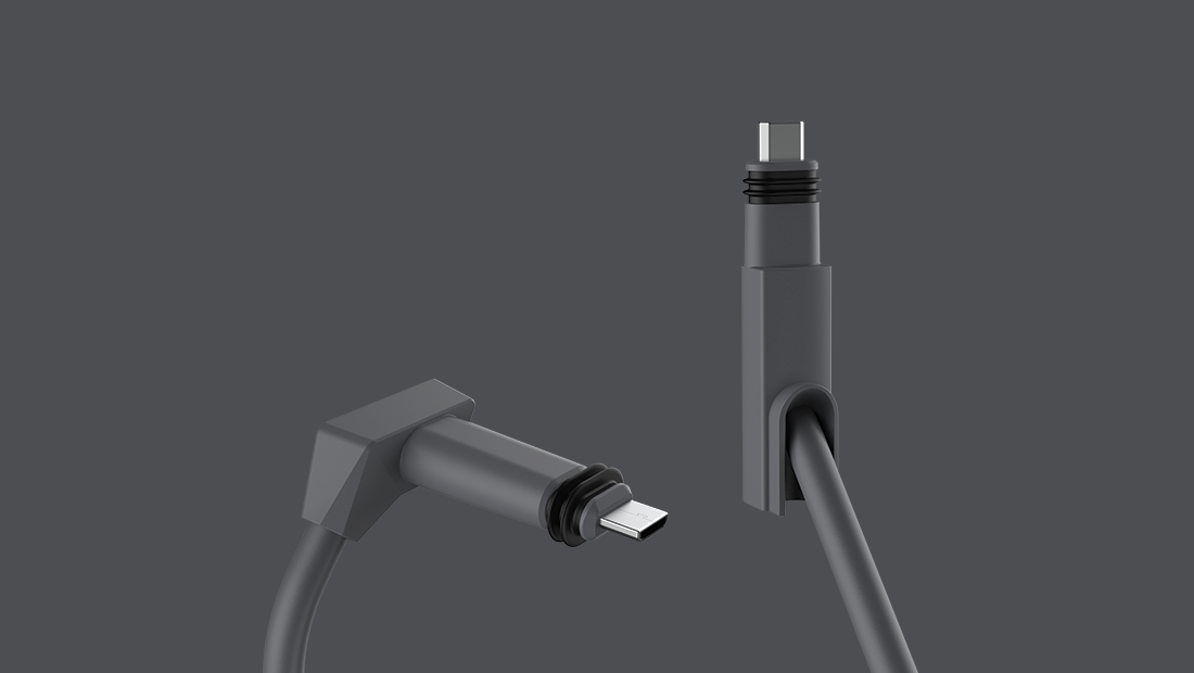
StarLink are bound by 60950-SELF and by the other cable rating standards (NEC, UL etc). If they put a consumer accessible RJ45 on the cable they also get limited by spec and limitations on RJ45, in particular a consumer connection to existing cabling (CAT5 and earlier) infrastructure. So far as I can make out that is where the 90W comes from. Using a proprietary connector removes the possibility of a consumer connection; either the cable has to be cut or the ends have to be ground off a USB-C socket (I intend to do the latter next). Presumably this is enough to remove the 90W/cable limit and, most likely, allow the router to put 120VA or more into the connector.

@WIMMPYIII
Copy link

I just didn't want to see you or anyone else go down a path of supplying lower wattage then the router itself supplies as it is already underpower to handle the dishy demands.

Well yes; I'm certainly not disputing the high power requirements of the antenna. What is more if the antenna is a purely passive PD then, as I understand it, none of the 802.3 PSEs will work at all; my understanding is that if the PSE cannot detect the 'signature' resistance on the PD then it can't put any voltage across the conductor pairs in the first place. If I can use an 802.3bt (which means iff the antenna does the negotiation) then I'd want to find a wiring method that didn't cause the PSE to drop the connection on heater overload and I suspect that isn't possible (the PSE has to drop both the channels, not just the one that overloads). Nevertheless I can turn the snow melt off (I don't need it) and 802.3bt has much better protections.

StarLink are bound by 60950-SELF and by the other cable rating standards (NEC, UL etc). If they put a consumer accessible RJ45 on the cable they also get limited by spec and limitations on RJ45, in particular a consumer connection to existing cabling (CAT5 and earlier) infrastructure. So far as I can make out that is where the 90W comes from. Using a proprietary connector removes the possibility of a consumer connection; either the cable has to be cut or the ends have to be ground off a USB-C socket (I intend to do the latter next). Presumably this is enough to remove the 90W/cable limit and, most likely, allow the router to put 120VA or more into the connector.

Please update us on how that goes.

Sign up for free to join this conversation on GitHub. Already have an account? Sign in to comment