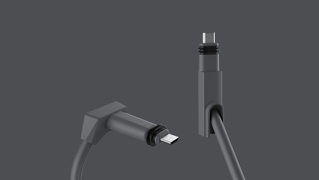
These are are some notes I put together on butchering the rectangular dishy cable.
FOLLOW THESE GUIDELINES AT YOUR OWN RISK. I TAKE NO RESPONSIBILITY FOR ANY DAMAGE OR INJURY YOU SUSTAIN FROM FOLLOWING OR NOT FOLLOWING THESE GUIDELINES.
In general, if you can get away with using the original 75' cable (or the official 150' long replacement cable), then that is ultimately preferable to doing any of this stuff. If you don't already know why you would want to do this then you definitely shouldn't do it. If you run into trouble, the first thing Starlink Support is going to ask is if the cable between your dishy and router has any modifications, and for good reason.
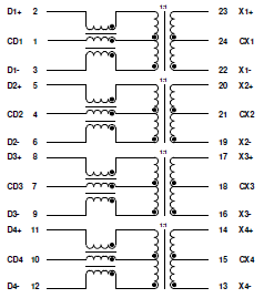
Despite the connectors being proprietary, the underlying technology connecting the router and the rectangular dishy is gigabit ethernet with non-standard PoE(The orange and green pairs are positive, the blue and brown pairs are negative). The cable itself is plain stranded STP CAT5e, suitable for outdoor use. The router acts as a 48V, 2A PoE power supply, so 96 watts are available at the port the router.
Stick with the original router (and possibly the ethernet port dongle) unless you have a good reason to try something else. You cannot power dishy with a standard PoE injector, but if you are enterprising enough you can rearrange the wires (swap blue/green, terminate as Type-B) going into and out-of a passive 4-pair PoE Injector and get it working with a sufficiently large 48V or 52V DC power supply.
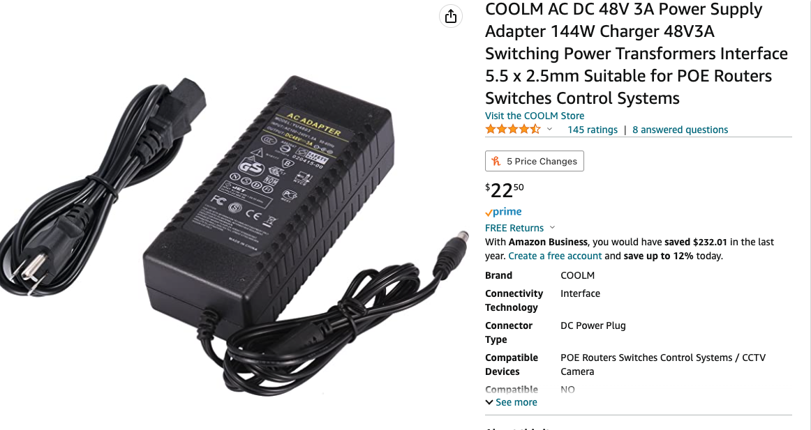
Note that most 48V 2A power supplies on Amazon are insufficient! I recommend this 52V power supply, as I have confirmed that it works and I am using it on my own 200+ft run.
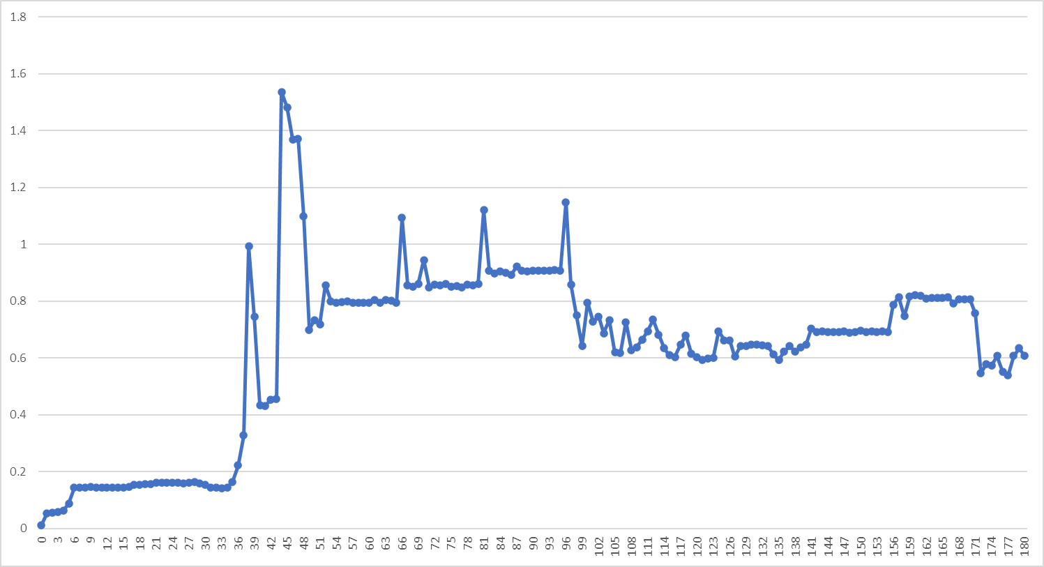
Resistance is the primary limiting factor you will run into. As you increase the length of the cable and add additional terminations/connectors, resistance increases. If the resistance is too high, the voltage at the dishy will (perhaps only occasionally) drop too low, causing it to spuriously reboot or not boot at all.
The exact maximum round-trip power resistance that the cable can have before Dishy's stability suffers isn't immediately clear, but 1.8Ω round-trip (~88 watts available for Dishy) appears to be stable while 2.5Ω round-trip is just barely unstable. (neither value includes the resistance of about 20 extra feet of the original CAT5e that is used in my setup)
If you cannot easily measure resistance, you will need to be as conservative as possible:
- Keep the length of your entire run as short as possible and your connectors as few as possible. Continuous runs are almost always preferable to runs with connectors.
- Use outdoor-rated cable for outdoor runs. If riser cable is all you have, paint it.
- Don't directly bury the cable unless it is rated for direct burial. Otherwise, water intrusion will eventually make your connection unreliable. The original cable is NOT rated for direct burial.
- Use 23AWG (or larger) CAT6/CAT6A cable, which will contribute around 0.03Ω/meter for a continuous run.
- The original cable was only 24AWG, so if you are using 23AWG cable then the less length you use from the original cable the better.
- It would appear that connectors will each contribute ~0.02-0.1Ω to the round-trip resistance, but more research is required.
- Avoid unnecessary use of patch panels, they introduce additional connectors and add resistance.
- 150' is likely the most distance you are going to get without changing your approach (like splitting out the power into larger guage wires, etc), but if you use a specialty low-resistance cable (like this) then you might be able to almost double that with some careful terminations.
- Once you get everything set up, try turning on snow pre-heat mode:
- If you can run a few speed tests in a row without problems, then you are likely golden.
- If your dishy reboots (either immediately or after running a few speed tests), your cable resistance is too high.
For longer runs you may need to use a power supply with a larger voltage. I can confirm that the rectangular dishy works fine on 52V.
With a longer run, proper grounding and surge protection becomes more important. Dishy must be grounded in some way. With the unmodified original cable, that grounding comes from the router. Since we are cutting that wire, we need to make sure that we provide that grounding.
- At least the the first RJ45 termination on the dishy side should be a grounded RJ45 plug.
- Use a high-quality, grounded, PoE-compatable ethernet surge
protector at the termination closest to your dishy.
- If you do this at your "service entrance" (where the wire enters your house), then you won't need a shielded ethernet cable after that point---but you might want it to be shielded to reduce RF interference.
- If you do use a shielded cable after the grounded surge protector, make sure you don't have a continuous ground between your surge protector and your Starlink router---that would create a ground loop, and you don't want that. If there is a ground fault, some of the surge current could go through your shielding!
- Alternatively, you could forgo the surge protector and use shielded cables, connectors, and plugs for the entire run and ensure continuity between the starlink router and dishy (presumably the router has some amount of built-in surge protection).


Hello All.
I want to do a similar thing.
To remove the starlink router, as i find it to limited in terms of configuration.
Besides that, i want to be able to connect most equipment via cable.
One issue, i am unable to order the provided PoE injector, as amazon does not list it anymore for sale.
Would the following one be a good option?
(ps i can only order from Amazon spain due to my location).
its 90W output, and has a power supply integrated.
A bit more€€€ but thats ok.
The idea is to put dishy V2 more or less 150 to 200 meters from my main house on a high support.
The PoE injector will only be used for powering Dishy V2. No other devices.
I have for that a uws-litle-16-PoE switch and a edgerouterx.
I am aware of the switching of the pairs to match up as well dishy and as well the PoE injector.
Trying to avoid bricking first connection of dishy ;) would be a shame after waiting so long...
Thank you
EDIT: I have at the moment the following injector:
48V 0.5A 24W PoE adapter from tp-link (TL-POE4824G). Its a passive 1 GB injector
If i can use this one, then it should be ok and i do not need to buy the more expensive mentioned.